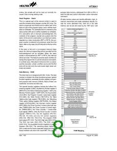
HT36A1
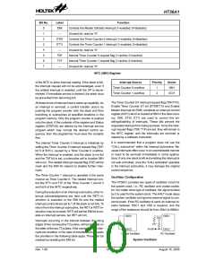
Bit No.
Label
EMI
¾
Function
Controls the Master (Global) interrupt (1=enabled; 0=disabled)
Unused bit, read as ²0²
0
1
2
3
4
5
6
7
ET0I
ET1I
¾
Controls the Timer Counter 0 interrupt (1=enabled; 0=disabled)
Controls the Timer Counter 1 interrupt (1=enabled; 0=disabled)
Unused bit, read as ²0²
T0F
T1F
¾
Internal Timer Counter 0 request flag (1=active; 0=inactive)
Internal Timer Counter 1 request flag (1=active; 0=inactive)
Unused bit, read as ²0²
INTC (0BH) Register
of the INTC to allow interrupt nesting. If the stack is full,
the interrupt request will not be acknowledged, even if
the related interrupt is enabled, until the SP is decre-
mented. If immediate service is desired, the stack must
be prevented from becoming full.
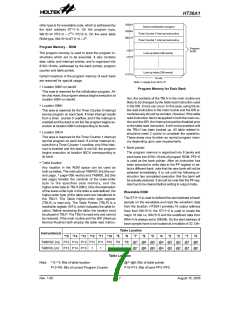
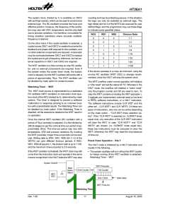
Interrupt Source
Timer Counter 0 overflow
Timer Counter 1 overflow
Priority
Vector
08H
1
2
0CH
The Timer Counter 0/1 interrupt request flag (T0F/T1F),
Enable Timer Counter 0/1 bit (ET0I/ET1I) and Enable
Master Interrupt bit (EMI) constitute an interrupt control
register (INTC) which is located at 0BH in the data mem-
ory. EMI, ET0I, ET1I are used to control the en-
abling/disabling of interrupts. These bits prevent the
requested interrupt from being serviced. Once the inter-
rupt request flags (T0F, T1F) are set, they will remain in
the INTC register until the interrupts are serviced or
cleared by a software instruction.
All these kinds of interrupt have a wake-up capability. As
an interrupt is serviced, a control transfer occurs by
pushing the program counter onto the stack and then
branching to subroutines at specified locations in the
program memory. Only the program counter is pushed
onto the stack. If the contents of the register and Status
register (STATUS) are altered by the interrupt service
program which may corrupt the desired control se-
quence, then the programmer must save the contents
first.
It is recommended that a program does not use the
²CALL subroutine² within the interrupt subroutine. Be-
cause interrupts often occur in an unpredictable manner
or need to be serviced immediately in some applica-
tions, if only one stack is left and enabling the interrupt is
not well controlled, once the ²CALL subroutine² operates
in the interrupt subroutine, it may damage the original
control sequence.
The internal Timer Counter 0 interrupt is initialized by
setting the Timer Counter 0 interrupt request flag (T0F;
bit 5 of INTC), caused by a Timer Counter 0 overflow.
When the interrupt is enabled, and the stack is not full
and the T0F bit is set, a subroutine call to location 08H
will occur. The related interrupt request flag (T0F) will be
reset and the EMI bit cleared to disable further inter-
rupts.
The Timer Counter 1 interrupt is operated in the same
manner as Timer Counter 0. The related interrupt con-
trol bits ET1I and T1F of the Timer Counter 1 are bit 3
and bit 6 of the INTC respectively.
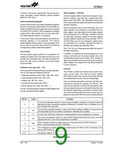
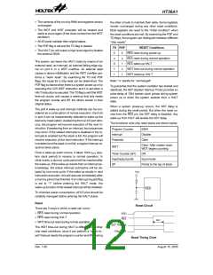
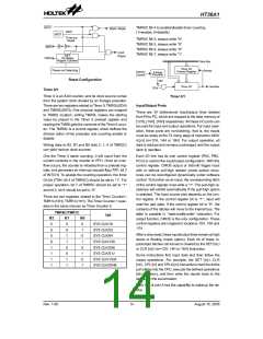
Oscillator Configuration
The HT36A1 provides two types of oscillator circuit for
the system clock, i.e., RC oscillator and crystal oscilla-
tor. No matter what type of oscillator, the signal divided
by 2 is used for the system clock. The HALT mode stops
the system oscillator and ignores external signal to con-
serve power. If the RC oscillator is used, an external re-
sistor between OSC1 and VSS is required, and the
range of the resistance should be from 30kW to 680kW.
During the execution of an interrupt subroutine, other in-
terrupt acknowledgments are held until the RETI in-
struction is executed or the EMI bit and the related
interrupt control bit are set to 1 (if the stack is not full). To
return from the interrupt subroutine, the RET or RETI in-
struction may be invoked. RETI will set the EMI bit to en-
able an interrupt service, but RET will not.
O
S
C
1
O
S
C
1
V
D
D
Interrupts occurring in the interval between the rising
edges of two consecutive T2 pulses, will be serviced on
the latter of the two T2 pulses, if the corresponding inter-
rupts are enabled. In the case of simultaneous requests
the priorities in the following table apply. These can be
masked by resetting the EMI bit.
f
S
Y
S
/
8
O
S
C
2
O
S
C
2
C
r
y
s
t
a
l
O
s
c
i
l
l
a
t
o
r
R
C
O
s
c
i
l
l
a
t
o
r
System Oscillator
Rev. 1.00
10
August 15, 2005

 HOLTEK [ HOLTEK SEMICONDUCTOR INC ]