BRER:
MOV.W
CMP.W
BNE
#H'0BB8, R4
;
R4,
R6
; Erase-verify executed 3000 times?
; If erase-verify not executed 3000 times, erase again
; If erase-verify executed 3000 times, branch to ABEND2
ERASE1
ABEND2
BRA
;———< Block address table used in erase-verify> ———
.ALIGN
ERVADR: .DATA.W
.DATA.W
2
H'0000
H'0080
H'0100
H'0180
H'0200
H'0400
H'0800
H'0C00
H'1000
H'2000
H'4000
H'6000
H'8000
; SB0
; SB1
; SB2
; SB3
; SB4
; SB5
; SB6
; SB7
; LB0
; LB1
; LB2
; LB3
; FLASH END
.DATA.W
.DATA.W
.DATA.W
.DATA.W
.DATA.W
.DATA.W
.DATA.W
.DATA.W
.DATA.W
.DATA.W
.DATA.W
EOWARI:
ABEND2:
Erase end
Erase error
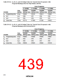
Loop Counter Values in Programs and Watchdog Timer Overflow Interval Settings: The
setting of #a, #b, #c, #d, and #e values in the programs depends on the clock frequency. Tables
19.9 (1) and (2) indicate sample loop counter settings for typical clock frequencies. However, #e is
set according to table 19.10.
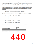
As a software loop is used, calculated values including percent errors may not be the same as
actual values. Therefore, the values are set so that the total programming time and total erase time
do not exceed 1 ms and 30 s, respectively.
The maximum number of writes in the program, N, is set to 50.
Programming and erasing in accordance with the flowcharts is achieved by setting #a, #b, #c, and
#d in the programs as shown in tables 19.9 (1) and (2). #e should be set as shown in table 19.10.
Wait state insertion is inhibited in these programs. If wait states are to be used, the setting should
be made after the program ends. The setting value for the watchdog timer (WDT) overflow time is
calculated based on the number of instructions between starting and stopping of the WDT,
including the write time and erase time. Therefore, no other instructions should be added between
starting and stopping of the WDT in this program example.
409

 HITACHI [ HITACHI SEMICONDUCTOR ]