ICL232
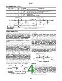
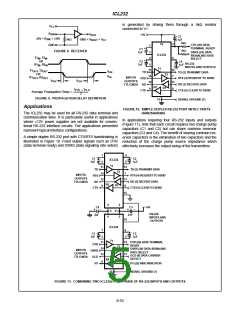
is generated by driving them through a 5kΩ resistor
connected to V+.
V
CC
R
XIN
R
+5V
OUT
C3
1µF
-
+
-30V < R
< +30V
XIN
GND < V
< V
CC
5kΩ
ROUT
5kΩ
2
6
16
GND
CTR (20) DATA
TERMINAL READY
1
+
C1
1µF
5kΩ
FIGURE 8. RECEIVER
3
4
DSRS (24) DATA
SIGNALING RATE
SELECT
-
ICL232
T1 , T2
IN IN
+
-
+
OR
R1 , R2
C2
1µF
C4
RS-232
1µF
5
-
IN
IN
INPUTS AND OUTPUTS
T1
11
14
T1
R1
, T2
OUT
OUT
V
TD
OH
TD (2) TRANSMIT DATA
RTS (4) REQUEST TO SEND
RD (3) RECEIVE DATA
OR
T2
V
10
12
7
OL
, R2
INPUTS
OUTPUTS
OUT
OUT
RTS
t
t
PLH
PHL
13
TTL/CMOS RD
R2
R1
9
8
t
t
PHL + PLH
2
CTS
CTS (5) CLEAR TO SEND
Average Propagation Delay =
FIGURE 9. PROPAGATION DELAY DEFINITION
15
SIGNAL GROUND (7)
Applications
FIGURE 10. SIMPLE DUPLEX RS-232 PORT WITH CTS/RTS
HANDSHAKING
The ICL232 may be used for all RS-232 data terminal and
communication links. It is particularly useful in applications
where ±12V power supplies are not available for conven-
tional RS-232 interface circuits. The applications presented
represent typical interface configurations.
In applications requiring four RS-232 inputs and outputs
(Figure 11), note that each circuit requires two charge pump
capacitors (C1 and C2) but can share common reservoir
capacitors (C3 and C4). The benefit of sharing common res-
ervoir capacitors is the elimination of two capacitors and the
reduction of the charge pump source impedance which
effectively increases the output swing of the transmitters.
A simple duplex RS-232 port with CTS/RTS handshaking is
illustrated in Figure 10. Fixed output signals such as DTR
(data terminal ready) and DSRS (data signaling rate select)
1
4
+
+
C1
C2
ICL232
T1
5
1µF
3
1µF
-
-
11
14
TD
RTS
RD
TD (2) TRANSMIT DATA
RTS (4) REQUEST TO SEND
RD (3) RECEIVE DATA
T2
10
12
7
INPUTS
OUTPUTS
TTL/CMOS
13
R2
R1
9
8
CTS
CTS (5) CLEAR TO SEND
15
6
6
2
2
C4
C3
+5V
RS-232
-
-
V- V+
2µF
2 µF
INPUTS AND
OUTPUTS
16
ICL232
T1
1
4
5
+
+
C1
1µF
C2
1µF
3
-
-
11
14 DTR (20) DATA TERMINAL
READY
7
DTR
DSRS
DCD
R1
T2
10
12
DSRS (24) DATA SIGNALING
RATE SELECT
DCD (8) DATA CARRIER
DETECT
INPUTS
OUTPUTS
TTL/CMOS
13
R2
R1
9
8
R1 (22) RING INDICATOR
15
SIGNAL GROUND (7)
FIGURE 11. COMBINING TWO ICL232s FOR 4 PAIRS OF RS-232 INPUTS AND OUTPUTS
8-53

 HARRIS [ HARRIS CORPORATION ]