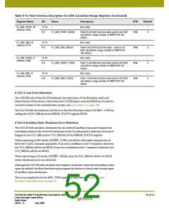
4.10.5.5 Line Based CRC Error Detection
The GS1559 will calculate line based CRC words for HD video signals for both the Y and
C data channels. These calculated CRC values are compared with the received CRC
values and any mismatch is flagged in the YCRC_ERR and/or CCRC_ERR bits of the
ERROR_STATUS register.
Line based CRC error flags will only be generated when the device is operating in HD
mode, (SD/HD = LOW).
If a CRC error is detected in the Y channel, the YCRC_ERR bit in the Error Status Register
will be set HIGH. If a CRC error is detected in the C channel, the CCRC_ERR bit in the
Error Status Register is set HIGH. Y and C CRC errors will also be generated if CRC values
are not received.
4.10.5.6 HD Line Number Error Detection
When operating in HD mode, the GS1559 will calculate line numbers based on the
timing generated by the internal Flywheel. These calculated line numbers are compared
with the received line numbers for the Y channel data and any mismatch is flagged in
the LNUM_ERR bit of the ERROR_STATUS.
Line Number Errors will also be generated if line number values are not received.
4.10.5.7 TRS Error Detection
TRS Errors Flags are generated by the GS1559 when:
1. The received TRS timing does not correspond to the internal Flywheel timing; or
2. The received TRS hamming codes are incorrect.
Both 8-bit and 10-bit SAV and EAV TRS words are checked for timing and data integrity
errors. These are flagged via the SAV_ERR and/or EAV_ERR bits of the ERROR_STATUS
register.
Timing-based TRS errors will only be generated if the FW_EN/DIS pin is set HIGH.
NOTE: In HD mode, (SD/HD = LOW), only the Y channel TRS codes will be checked for
errors.
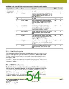
4.10.6 Error Correction and Insertion
In addition to Signal Error Detection and Indication, the GS1559 may also correct certain
types of errors by inserting corrected code words, checksums and CRC values into the
data stream. These features are only available in SMPTE mode and IOPROC_EN/DIS
must be set HIGH. Individual correction features may be enabled or disabled via the
IOPROC_DISABLE register (Table 4-14).
All of the IOPROC_DISABLE register bits default to 'zero' after device reset, enabling all
of the processing features. To disable any individual error correction feature, the Host
Interface must set the corresponding bit HIGH in the IOPROC_DISABLE register.
GS1559 HD-LINX™ II Multi-Rate Deserializer with
Loop-Through Cable Driver
Data Sheet
53 of 71
30572 - 8
July 2008

 GENNUM [ GENNUM CORPORATION ]