Page ꢁ
2. Pin Out
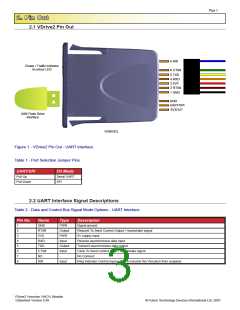
2.1 VDrive2 Pin Out
8 RI#
Power / Traffic Indicator
bi-colour LED
6 CTS#
5 TXD
4 RXD
3 5V0
2 RTS#
1 GND
GND
UART/SPI
3V3OUT
USB Flash Drive
interface
VDRIVE2
Figure 1 - VDrive2 ꢌin ꢆut - �ꢄꢋT interꢇace.
Taꢁle 1 - ꢌort ꢂelection ꢊumper ꢌins
UART/SPI
ꢌull-�p
I/O Mode
ꢂerial �ꢄꢋT
ꢂꢌI
ꢌull-Down
2.2 UART Interface Signal Descriptions
Taꢁle 2 - Data and Control us ꢂignal Mode ꢆptions - �ꢄꢋT Interꢇace
Pin No.
Name
GND
RTS#
ꢍV0
Type
ꢌWꢋ
ꢆutput
ꢌWꢋ
Input
ꢆutput
Input
-
Description
1
2
3
4
ꢍ
6
7
8
ꢂignal ground
ꢋequest To ꢂend Control ꢆutput / Handshaꢅe signal
ꢍV supply input
ꢋXD
TXD
CTS#
NC
ꢋeceive asynchronous data input
Transmit asynchronous data output
Clear To ꢂend Control Input / Handshaꢅe signal
No Connect
RI#
Input
ꢋing Indicator Control Input. �sed to resume the Vinculum ꢇrom suspend.
VDrive2 Vinculum VNC1L Module
Datasheet Version 0.99
© Future Technology Devices International Ltd. 2007

 FTDI [ FUTURE TECHNOLOGY DEVICES INTERNATIONAL LTD. ]