FT260 HID-CLASS USB TO UART/I2C BRIDGE IC
Version 1.1
Document No.: FT_001272 Clearance No.: FTDI#484
The UART provides a transmitter enable control signal (TX_ACTIVE) on the pin DIO0 to assist with
interfacing to RS485 transceivers. The UART can support baud rates from 1.2 Kbaud to 12 Mbaud.
UART in the FT260 functions include:
Full RS232 support
7 or 8 data bits, an optional parity bit and 1 or 2 stop bits support
Baud rate from 1.2 Kbaud to 12 Mbaud support
Baud rate accuracy within +-1.5%
Optional hardware flow control via RTS / CTS and DTR / DSR
Optional software flow control via XON / XOFF characters
I2C Master Controller. I2C (Inter Integrated Circuit) is a multi-master serial bus invented by Philips. I2C
uses two bi-directional open-drain wires called serial data (SDA) and serial clock (SCL). Common I2C bus
speeds are the standard mode (SM) with bit rate up to 100 Kbit/s, fast mode (FM) with the bit rate up to
400 Kbit/s, Fast mode plus (FM+) with the bit rate up to 1 Mbit/s, and High Speed mode (HS) with the bit
rate up to 3.4 Mbit/s. Refer to the I2C specification for more information on the protocol.
The FT260 device can operates as I2C master, and the major functions include:
Fully compatible to v2.1 and v3 specification
7-bit address support
Support 4 speed configurations defined in I2C-bus specification
Support bit rate up to 3Mbit/s
Clock stretching support
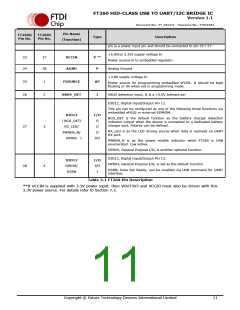
GPIOs. The FT260 contains 14 digital function pins. Each pin can be set as I2C/UART related function or
GPIO (General Purpose Input/Output). Some GPIO functions are implemented in the FT260 for various
applications like TX_ACTIVE, TX_LED, RX_LED for UART; SUSPOUT_N, WAKEUP for USB; PWREN and
BCD_DET indicator for power management. GPIO functions can also be directly controlled by applications
over USB via the Control pipe. The drive strength, slew rate control and pull high/low resistors can be
configured in the Vendor Specific Parameters defined in embedded eFUSE or external EEPROM by
FT_PROG.
GPIO functions for each pin in the FT260 include:
DIO0 (pin 7 @ WQFN28) can be configured as TX_ACTIVE, TX_LED, GPIOA
DIO1 (pin 8 @ WQFN28) will be set as GPIOB function by default
DIO2 (pin 9 @ WQFN28) will be set as GPIOE function by default
DIO3 (pin 10 @ WQFN28) will be set as GPIOC function by default when the UART interface in
not enabled
DIO4 (pin 11 @ WQFN28) will be set as GPIOD function by default when the UART interface in
not enabled
DIO5 (pin 12 @ WQFN28) can be set as GPIO0 function when the I2C interface and external
EEPROM are not supported
DIO6 (pin 13 @ WQFN28) can be set as GPIO1 function when the I2C interface and external
EEPROM are not supported
DIO7 (pin 14 @ WQFN28) can be configured as SUSPOUT_N, SUSPOUT, PWREN_N, GPIO2
Copyright © Future Technology Devices International Limited
15

 FTDI [ FUTURE TECHNOLOGY DEVICES INTERNATIONAL LTD. ]