FT2232C Dual USB UART / FIFO I.C.
5.2 IO Pin Definitions by Chip Mode
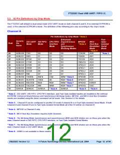
The FT2232C will default to dual serial mode (232 UART mode on both channel A and B, if no external EEPROM is
used, or the external EEPROM is blank. The definition of the following pins vary according to the chip’s mode :-
Channel A
Pin Definitions by Chip Mode **Note 2
Enhanced
Fast
Opto-
Host Bus Isolated
Emulation Serial
Generic
Pin
Name
232 UART 245 FIFO CPU FIFO Asynchronous
MPSSE
**Note 4
MCU
Pin#
Mode
Mode
Interface
Mode
and
Synchronous
Bit-Bang Modes
Mode
Mode
**Note 5
24
23
22
21
20
19
17
16
15
13
12
11
10
ADBUS0 TXD
D0
D0
D0
TCK/SK
TDI/D0
AD0
**Note 3
ADBUS1 RXD
ADBUS2 RTS#
ADBUS3 CTS#
ADBUS4 DTR#
ADBUS5 DSR#
ADBUS6 DCD#
ADBUS7 RI#
D1
D1
D1
AD1
D2
D2
D2
TDO/DI
TMS/CS
GPIOL0
GPIOL1
GPIOL2
GPIOL3
GPIOH0
GPIOH1
GPIOH2
GPIOH3
**Note 8
AD2
D3
D3
D3
AD3
D4
D4
D4
AD4
D5
D5
D5
AD5
D6
D6
D6
AD6
D7
D7
D7
AD7
ACBUS0 TXDEN
ACBUS1 SLEEP#
ACBUS2 RXLED#
ACBUS3 TXLED#
RXF#
TXE#
RD#
WR
SI/WUA
CS#
A0
WR# **Note 6
RD# **Note 6
WR# **Note 7
RD# **Note 7
SI/WUA
I/O0
I/O1
RD#
WR#
**Note 8
IORDY
OSC
**Note 8
SI/WUA
SI/WUA
**Note 2 : 232 UART, 245 FIFO, CPU FIFO Interface, and Fast Opto-Isolated modes are enabled in the external
EEPROM. Enhanced Asynchronous and Synchronous Bit-Bang modes, MPSSE, and MCU Host Bus Emulation
modes are enabled using the driver command set bit mode. See Section 5.2 for details.
**Note 3 : Channel A can be configured in another IO mode if channel B is in Fast Opto-Isolated Serial Mode. If both
Channel A and Channel B are in Fast Opto-Isolated Serial Mode all of the IO will be on Channel B.
**Note 4 : MPSSE is Channel A only.
**Note 5 : MCU Host Bus Emulation requires both Channels.
**Note 6 : The Bit-Bang Mode (synchronous and asynchronous) WR# and RD# strobes are on these pins when the
main Channel mode is 245 FIFO, CPU FIFO interface, or Fast Opto-Isolated Serial Modes.
**Note 7 : The Bit-Bang Mode (synchronous and asynchronous) WR# and RD# strobes are on these pins when the
main Channel mode is 232 UART Mode.
**Note 8 : SI/WU is not available in these modes.
DS2232C Version 1.2
© Future Technology Devices International Ltd. 2004
Page 12 of 54

 FTDI [ FUTURE TECHNOLOGY DEVICES INTERNATIONAL LTD. ]