Freescale Semiconductor, Inc.
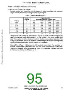
RCKB — SCI Baud Rate Clock Check (Test)
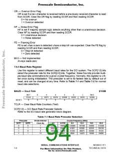
SCR[2:0] — SCI Baud Rate Selects
Selects receiver and transmitter bit rate based on output from baud rate prescaler
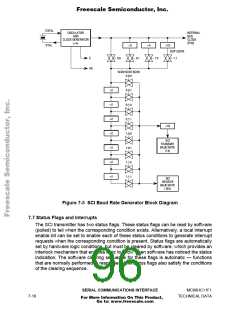
stage. Refer to the SCI baud rate generator block diagram.
Table 7-2 Baud Rate Selection
Divide
Highest Baud Rate
Prescaler
(Prescaler Output from Previous Table)
SCR[2:0]
0 0 0
0 0 1
0 1 0
0 1 1
1 0 0
1 0 1
1 1 0
1 1 1
By
1
4800
4800
2400
1200
600
300
150
75
19200
19200
9600
4800
2400
1200
600
76800
76800
38400
19200
9600
4800
2400
1200
600
312500
312500
156250
78125
39063
19531
9766
2
4
8
16
32
64
128
300
4883
—
150
2441
The prescaler bits, SCP[2:0], determine the highest baud rate, and the SCR[2:0] bits
select an additional binary submultiple (≥1, ≥2, ≥4, through ≥128) of this highest baud
rate. The result of these two dividers in series is the 16X receiver baud rate clock. The
SCR[2:0] bits are not affected by reset and can be changed at any time, although they
should not be changed when any SCI transfer is in progress.
Figure 7-3 and Figure 7-4 illustrate the SCI baud rate timing chain. The prescaler se-
lect bits determine the highest baud rate. The rate select bits determine additional di-
vide by two stages to arrive at the receiver timing (RT) clock rate. The baud rate clock
is the result of dividing the RT clock by 16.
SERIAL COMMUNICATIONS INTERFACE
TECHNICAL DATA
7-9
For More Information On This Product,
Go to: www.freescale.com

 FREESCALE [ Freescale ]