Freescale Semiconductor, Inc.
When the SPI system is configured as a master and the SS input line goes to active
low, a mode fault error has occurred — usually because two devices have attempted
to act as master at the same time. In cases where more than one device is concurrent-
ly configured as a master, there is a chance of contention between two pin drivers. For
push-pull CMOS drivers, this contention can cause permanent damage. The mode
fault mechanism attempts to protect the device by disabling the drivers. The MSTR
control bit in the SPCR and all four DDRD control bits associated with the SPI are
cleared and an interrupt is generated subject to masking by the SPIE control bit and
the I bit in the CCR.
Other precautions may need to be taken to prevent driver damage. If two devices are
made masters at the same time, mode fault does not help protect either one unless
one of them selects the other as slave. The amount of damage possible depends on
the length of time both devices attempt to act as master.
A write collision error occurs if the SPDR is written while a transfer is in progress. Be-
cause the SPDR is not double buffered in the transmit direction, writes to SPDR cause
data to be written directly into the SPI shift register. Because this write corrupts any
transfer in progress, a write collision error is generated. The transfer continues undis-
turbed, and the write data that caused the error is not written to the shifter.
A write collision is normally a slave error because a slave has no control over when a
master initiates a transfer. A master knows when a transfer is in progress, so there is
no reason for a master to generate a write-collision error, although the SPI logic can
detect write collisions in both master and slave devices.
The SPI configuration determines the characteristics of a transfer in progress. For a
master, a transfer begins when data is written to SPDR and ends when SPIF is set.
For a slave with CPHA equal to zero, a transfer starts when SS goes low and ends
when SS returns high. In this case, SPIF is set at the middle of the eighth SCK cycle
when data is transferred from the shifter to the parallel data register, but the transfer
is still in progress until SS goes high. For a slave with CPHA equal to one, transfer be-
gins when the SCK line goes to its active level, which is the edge at the beginning of
the first SCK cycle. The transfer ends in a slave in which CPHA equals one when SPIF
is set.
8.5 SPI Registers
The three SPI registers, SPCR, SPSR, and SPDR, provide control, status, and data
storage functions. Refer to the following information for a description of how these reg-
isters are organized.
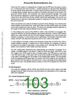
8.5.1 Serial Peripheral Control
SPCR — Serial Peripheral Control Register
$1028
Bit 7
SPIE
0
6
SPE
0
5
DWOM
0
4
MSTR
0
3
CPOL
0
2
CPHA
1
1
SPR1
U
Bit 0
SPR0
U
RESET:
SERIAL PERIPHERAL INTERFACE
TECHNICAL DATA
8-5
For More Information On This Product,
Go to: www.freescale.com

 FREESCALE [ Freescale ]