Computer Operating Properly (COP)
COP Control Register
6.3.5 Reset Vector Fetch
A reset vector fetch occurs when the vector address appears on the data bus. A
reset vector fetch clears the SIM counter.
6.3.6 COPD (COP Disable)
The COPD signal reflects the state of the COP disable bit (COPD) in the
configuration register (CONFIG). See Section 5. Configuration Register
(CONFIG).
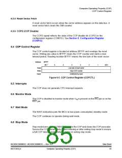
6.4 COP Control Register
The COP control register is located at address $FFFF and overlaps the reset
vector. Writing any value to $FFFF clears the COP counter and starts a new
timeout period. Reading location $FFFF returns the low byte of the reset vector.
Address:
$FFFF
Bit 7
6
5
4
3
2
1
Bit 0
Read:
Write:
Reset:
Low byte of reset vector
Clear COP counter
Unaffected by reset
Figure 6-3. COP Control Register (COPCTL)
6.5 Interrupts
The COP does not generate CPU interrupt requests.
6.6 Monitor Mode
The COP is disabled in monitor mode when VHI is present on the IRQ pin or on the
RST pin.
6.7 Wait Mode
6.8 Stop Mode
The WAIT instruction puts the MCU in low power-consumption standby mode.
The COP continues to operate during wait mode.
Stop mode turns off the CGMXCLK input to the COP and clears the COP prescaler.
Service the COP immediately before entering or after exiting stop mode to ensure
a full COP timeout period after entering or exiting stop mode.
MC68HC908MR32 • MC68HC908MR16 — Rev. 6.0
MOTOROLA Computer Operating Properly (COP)
Data Sheet
85

 FREESCALE [ Freescale ]