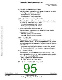
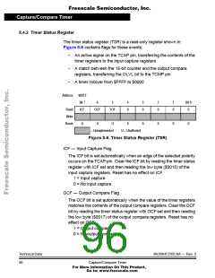
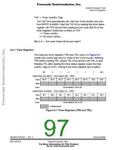
Freescale Semiconductor, Inc.
Capture/Compare Timer
Timer I/O Registers
Bit 7
6
5
4
3
2
1
Bit 0
Bit 8
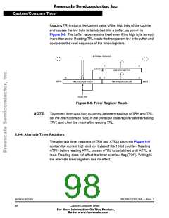
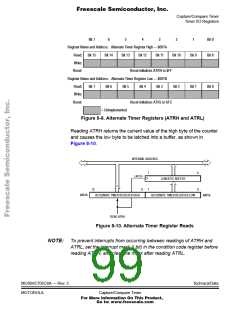
Register Name and Address: Alternate Timer Register High — $001A
Read: Bit 15
Write:
Bit 14
Bit 13
Bit 12
Bit 11
Bit 10
Bit 9
Reset:
Reset initializes ATRH to $FF
Register Name and Address: Alternate Timer Register Low — $001B
Read:
Write:
Reset:
Bit 7
Bit 6
Bit 5
Bit 4
Bit 3
Bit 2
Bit 1
Bit 0
Reset initializes ATRL to $FC
= Unimplemented
Figure 8-9. Alternate Timer Registers (ATRH and ATRL)
Reading ATRH returns the current value of the high byte of the counter
and causes the low byte to be latched into a buffer, as shown in
Figure 8-10.
INTERNAL DATA BUS
7
7
0
0
LATCH
8
LOW BYTE BUFFER
15
$001A
ALTERNATE TIMER REGISTER HIGH
ALTERNATE TIMER REGISTER LOW
$001B
READ ATRH
Figure 8-10. Alternate Timer Register Reads
NOTE: To prevent interrupts from occurring between readings of ATRH and
ATRL, set the interrupt mask (I bit) in the condition code register before
reading ATRH, and clear the mask after reading ATRL.
MC68HC705C8A — Rev. 3
MOTOROLA
Technical Data
Capture/Compare Timer
For More Information On This Product,
Go to: www.freescale.com

 FREESCALE [ Freescale ]