Freescale Semiconductor, Inc.
Interrupts
Interrupt Processing
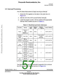
4.4 Interrupt Processing
The CPU takes these actions to begin servicing an interrupt:
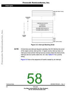
1. Stores the CPU registers on the stack in the order shown in
Figure 4-4
2. Sets the I bit in the CCR to prevent further interrupts
3. Loads the program counter with the contents of the appropriate
interrupt vector locations as shown in Table 4-1.
Table 4-1. Reset/Interrupt Vector Addresses
Local
Mask
Global
Mask
Priority
(1 = Highest)
Function
Source
Vector Address
Power-on
logic
Reset
None
None
1
$1FFE–$1FFF
RESET pin
Software
interrupt
(SWI)
Same priority
as any
instruction
User code
None
None
None
I bit
$1FFC–$1FFD
$1FFA–$1FFB
IRQ pin
Port B pins
ICF bit
External
interrupt
2
3
ICIE bit
OCIE bit
TOIE bit
Timer
interrupts
OCF bit
TOF bit
I bit
$1FF8–$1FF9
TDRE bit
TC bit
TCIE bit
SCI
interrupts
RDRF bit
OR bit
I bit
I bit
4
5
$1FF6–$1FF7
$1FF4–$1FF5
RIE bit
ILIE bit
SPIE
IDLE bit
SPIF bit
MODF bit
SPI
interrupts
The return-from-interrupt (RTI) instruction causes the CPU to recover
the CPU registers from the stack as shown in Figure 4-4.
MC68HC705C8A — Rev. 3
MOTOROLA
Technical Data
Interrupts
For More Information On This Product,
Go to: www.freescale.com

 FREESCALE [ Freescale ]