ELECTRICAL CHARACTERISTICS
DYNAMIC ELECTRICAL CHARACTERISTICS
Table 4. Dynamic Electrical Characteristics (continued)
Characteristics noted under conditions 7.0 V ≤ VSUP ≤ 18 V, -40°C ≤ TA ≤ 125°C, GND = 0 V unless otherwise noted. Typical
values noted reflect the approximate parameter means at TA = 25°C under nominal conditions unless otherwise noted.
Characteristic
Symbol
Min
Typ
Max
Unit
Non Differential Slew Rate (CANL or CANH)
V/µs
Slew Rate 3
Slew Rate 2
Slew Rate 1
Slew Rate 0
t
t
t
t
4.0
3.0
2.0
1.0
19
13.5
8.0
40
20
15
10
SL3
SL2
SL1
SL0
5.0
Latch
RST
WU
OUT
Counter
CANH
CANL
Pulse OK
Pulse Width
Filter
RST
+
WU Receiver
Timeout
Narrow
Pulse
Timeout
Generator
Standby
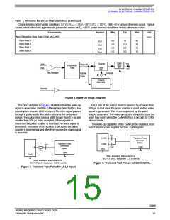
Figure 4. Wake-Up Block Diagram
The block diagram in Figure 4 illustrates how the wake-up
signal is generated. First the CAN signal is detected by a low
consumption receiver (WU receiver). Then the signal passes
through a pulse width filter which discards the undesired
pulses. The pulse must have a width bigger than 0.5 µs and
smaller than 500 µs to be accepted. When a pulse is
discarded the pulse counter is reset and no wake signal is
generated, otherwise when a pulse is accepted the pulse
counter is incremental and after three pulses the wake signal
is asserted.
Each one of the pulses must be spaced by no more than
500 µs. In that case the pulse counter is reset and no wake
signal is generated. This is accomplished by the wake
timeout generator. The wake-up cycle is completed (and the
wake flag reset) when the CAN interface is brought to CAN
Normal mode.
The wake-up capability of the CAN can be disabled, refer
to SPI interface and register section, CAN register.
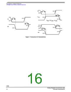
1nF
CANH
Transient Pulse
Generator
(Note)
Transient Pulse
1nF
CANL
GND
Generator
(Note)
1nF
GND
LX
10 k
GND
GND
Note: Waveform in accordance to
ISO 7637 part1, test pulses 1, 2, 3a and 3b.
Note: Waveform in accordance to
ISO 7637 part1, test pulses 1, 2, 3a and 3b.
Figure 6. Transient Test Pulses for CANH/CANL
Figure 5. Transient Test Pulse for L0:L3 Inputs
33989
Analog Integrated Circuit Device Data
Freescale Semiconductor
15

 FREESCALE [ Freescale ]