Blood Pressure Monitor
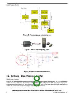
Figure 6. Pressure gauge block diagram
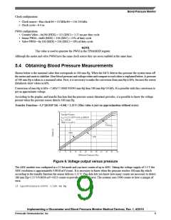
Figure 7. Motor, mini air pump, valve
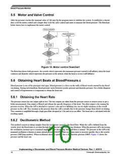
Figure 8. Pressure sensor connection
5.3 Software—Blood Pressure Monitor
BloodPressureMonitor.c
In this file are the determined incremented and decremented states to start to measure blood pressure. The PWM configuration
controls the motor and the valve. The timer/pulse width modulator (TPM) configuration as PWM edge-aligned using channel
0 for motor control and channel 1 for valve control is described below. There are also some values used for the motor and valve
control. The values can be changed depending on the hardware implementation.
Implementing a Glucometer and Blood Pressure Monitor Medical Devices, Rev. 1, 4/2010
8
Freescale Semiconductor, Inc.

 FREESCALE [ Freescale ]