Blood Pressure Monitor
Clock configuration:
• Clock source—Bus clock/64 = 10 MHz/64 = 156.250 kHz
• Clock cycle—6.4 us
PWM configuration:
• Counter Value—0x200 (HEX) = 512 (DEC) = 3.27 ms per duty cycle
• Motor PWM—0x80 (HEX) = 128 (DEC) = 25% of duty cycle
• Valve PWM—0x 100 (HEX) = 256 (DEC) = 50% of duty cycle
NOTE
This value is used to generate the PWM in the TPMxMOD register.
Although the motor and valve PWM have the same clock source they are never enabled at the same time.
5.4 Obtaining Blood Pressure Measurements
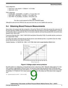
Shown below is the maximal value that corresponds to 180 mm Hg. When the MCU detects this pressure the system turns off
the motor and starts to stabilize. How blood pressure and voltage relate and compare to each other is explained below. A pressure
of 180 mm Hg is taken as a maximal value. First, it is necessary to make the conversion from mm Hg to kPa, because the sensor
datasheets show values in kPa.
Conversion of mm Hg to kPa—1 kPa=7.50061505043 mm Hg then 180 mm Hg=24 kPa. It is possible with this conversion to
get an approximate voltage.
According to the graphic and transfer function that the pressure sensor datasheet provides, it is possible to know the voltage
present when the pressure sensor detects 180 mm Hg.
Transfer Function—3.3*[(0.018*24) + 0.04] = 1.55 V (This value is just an approximation without error)
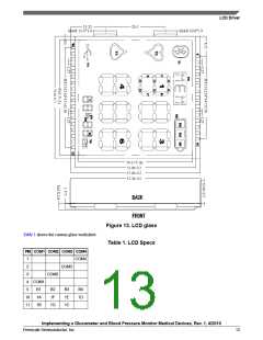
Figure 9. Voltage output versus pressure
The ADC module was configured in a 12-bit mode and can have counts of up to 4095. Taking the voltage supply of 3.3 V the
ADC resolution is approximately 0.8058 mV/count . It is necessary to know when the pressure reaches 180 mm Hg which
according to the transfer function the sensor delivers 1.55 V. This data lets you know how many counts are necessary to detect
180 mm Hg=1.55 V/0.8058 mV=1923 counts to provide a range of error. The systems uses 1900 counts to have a margin of
error.
if (gu16Pressure>1900) //180 mm Hg
Implementing a Glucometer and Blood Pressure Monitor Medical Devices, Rev. 1, 4/2010
Freescale Semiconductor, Inc.
9

 FREESCALE [ Freescale ]