Blood Glucose Monitor
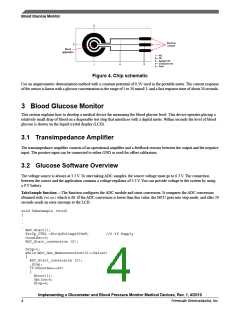
Figure 4. Chip schematic
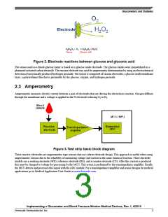
Use an amperometric determination method with a constant potential of 0.3V used in the portable meter. The current response
of the sensor is linear with a glucose concentration in the range of 5 to 30 mmol/ L and a fast response time of about 20 seconds.
3 Blood Glucose Monitor
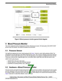
This section explains how to develop a medical device for measuring the blood glucose level. This device operates placing a
relatively small drop of blood on a disposable test strip that interfaces with a digital meter. Within seconds the level of blood
glucose is shown on the liquid crystal display (LCD).
3.1 Transimpedance Amplifier
The transimpedance amplifier consists of an operational amplifier and a feedback resistor between the output and the negative
input. The positive input can be connected to either GND or used for offset calibration.
3.2 Glucose Software Overview
The voltage source is always at 3.3 V. To start taking ADC samples, the source voltage must go to 0.3 V. The connection
between the source and the application contains a voltage regulator of 3.3 V. You can provide voltage to the system by using
a 9 V battery.
TakeSample function —The function configures the ADC module and starts conversion. It compares the ADC conversion
obtained with Value1which is 60. If the ADC conversion is lower than this value, the MCU goes into stop mode, and after 20
seconds sends an error message to the LCD.
void TakeSample (void)
{
.
.
.
ADC_Start();
Strip_CTRL =StripVoltage300mV;
CountSec=0;
ADC_Start_conversion (2);
//0.3V Supply
Drop=1;
while(ADC_Get_Newconversion(2)<=Value1)
{
ADC_Start_conversion (2);
_Stop;
if(CountSec==20)
{
Error(1);
Option=6;
Drop=0;
Implementing a Glucometer and Blood Pressure Monitor Medical Devices, Rev. 1, 4/2010
4
Freescale Semiconductor, Inc.

 FREESCALE [ Freescale ]