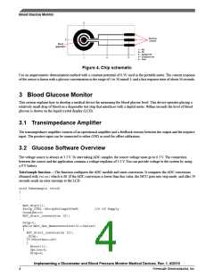
Blood Glucose Monitor
break;
}
}
If no errors occur. The ADC conversion continues and sets the ranges as shown in the code below. The samples obtained must
be the following:
• Range 0— ADC Conversion < 128,
• Range 1— 141 < ADC Conversion <= 292
• Range 2— 239 < Range 2 ADC Conversion<=407
• Range 3— 408 < Range 3 ADC Conversion<= 537
• Range 4— 539 < Range 4 ADC Conversion<= 752
• Range 5— ADC Conversion >752. Indicates a high level of glucose
NOTE
The ADC module resolution is 0.8058 mV/count.
while(CountSec<6)
{
bLCD_CharPosition = 10;
vfnLCD_Write_Char (0x30+(5-CountSec));
if(CountSec==1)
{
ADC_Start_conversion (2);
Sample=ADC_Get_Newconversion(2);
if(Sample<128)
{
bLCD_CharPosition = 0;
vfnLCD_Write_Char ('0');
Range=0;
}
.
.
.
}
The code below sets the glucose levels for each range. You have to change the information in range 2, range 3, and range 4 in
the lines as commented below. Finally, determine the glucose level with the equation:
Glucose = x + midpoint
The x variable for:
• Range 1 = 35
• Range 2 = 86
• Range 3 = 166
• Range 4 = 201
if(Range==1) // changes for 2, 3 or 4
{
low=0;
high=51;
midpoint=0;
while (low<high)
{
midpoint =(low+high)/2;
if (Sample<Range1[midpoint]) // changes for Range2, Range3 or Range4
{
high=midpoint-1;
}
else
{
low=midpoint+1;
}
}
Glucose=35+midpoint;
Implementing a Glucometer and Blood Pressure Monitor Medical Devices, Rev. 1, 4/2010
Freescale Semiconductor, Inc.
5

 FREESCALE [ Freescale ]