User Guide
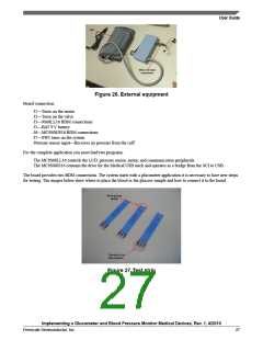
Figure 26. External equipment
Board connection:
J1—Turns on the motor
J2—Turns on the valve
J3—9S08LL16 BDM connections
J5—BAT 9 V battery
J6—MC9S08JS16 BDM connections
J7—SW1 turns on the system
Pressure sensor input—Receives air pressure from the cuff
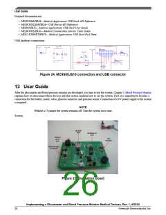
For the complete application you must load two programs.
The MC9S08LL16 controls the LCD, pressure sensor, motor, and communication peripherals.
The MC9S08JS16 contains the drive for the Medical USB stack and operates as a bridge from the SCI to USB.
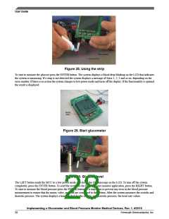
The board provides two BDM connections. The system starts with a glucometer application it is necessary to have new strips
for testing. The images below show where to place the blood or the glucose sample and how to connect it to the board.
Figure 27.Test strip
Implementing a Glucometer and Blood Pressure Monitor Medical Devices, Rev. 1, 4/2010
Freescale Semiconductor, Inc.
27

 FREESCALE [ Freescale ]