Freescale Semiconductor, Inc.
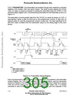
7.3.2.1 TRANSMITTER. The transmitters are enabled through their respective command
registers (CR) located within the serial module. The serial module signals the CPU32
when it is ready to accept a character by setting the transmitter-ready bit (TxRDY) in the
channel's status register (SR). Functional timing information for the transmitter is shown in
Figure 7-5.
The transmitter converts parallel data from the CPU32 to a serial bit stream on TxDx. It
automatically sends a start bit followed by the programmed number of data bits, an
optional parity bit, and the programmed number of stop bits. The least significant bit is
sent first. Data is shifted from the transmitter output on the falling edge of the clock
source.
C1 IN
TRANSMISSION
TxDx
C1
C2
C3
C4
BREAK
C6
TRANSMITTER
ENABLED
TxRDY
(SR2)
W
W
W
W
W
W
W
W
CS
C5
C1
C2
C3
START
BREAK
C4
STOP
BREAK
C6
NOT
TRANSMITTED
1
CTS
MANUALLY ASSERTED
BY BIT- SET COMMAND
MANUALLY
ASSERTED
2
RTS
NOTES:
1. TIMING SHOWN FOR MR2(4) = 1
2. TIMING SHOWN FOR MR2(5) = 1
3. C = TRANSMIT CHARACTER
N
4. W = WRITE
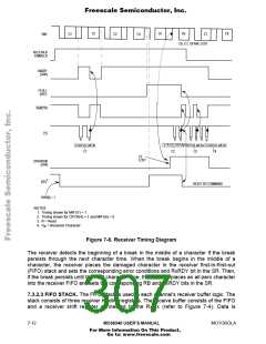
Figure 7-5. Transmitter Timing Diagram
Following transmission of the stop bits, if a new character is not available in the transmitter
holding register, the TxDx output remains high ('mark' condition), and the transmitter
empty bit (TxEMP) in the SR is set. Transmission resumes and the TxEMP bit is cleared
when the CPU32 loads a new character into the transmitter buffer (TB). If a disable
command is sent to the transmitter, it continues operating until the character in the
7- 10
MC68340 USER’S MANUAL
MOTOROLA
For More Information On This Product,
Go to: www.freescale.com

 FREESCALE [ Freescale ]