Freescale Semiconductor, Inc.
1
2
3
4
5
4
6
7
8
9
0
1
2
3
CLOCK
1 PRE-
FETCH
3 PRE-
FETCH
4 PRE-
FETCH
BUS
CONTROLLER
2 PRE-
FETCH
WRITE
FOR 4
WRITE
FOR 4
INSTRUCTION
CONTROLLER
OFFSET
CALC
NOT
TAKEN
MOVE TO
(A0)
MOVEQ
CMP
MOVEQ
#7,D1
EXECUTION
TIME
CMP
D1,D0
BLE.B NOT TAKEN
MOVE.L D1,(AO)
Figure 5-35. Example 2—Branch Not Taken
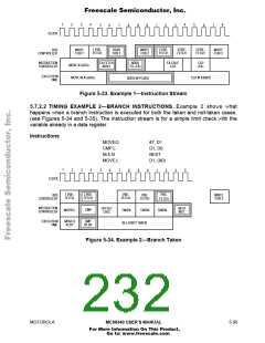
5.7.2.3 TIMING EXAMPLE 3—NEGATIVE TAILS. This example (see Figure 5-36) shows
how to use negative tail figures for branches and other change-of-flow instructions. In this
example, bus speed is assumed to be four clocks per access. Instruction three is at the
branch destination.
Although the CPU32 has a two-word instruction pipeline, internal delay causes minimum
branch instruction time to be three bus cycles. The negative tail is a reminder that an extra
two clocks are available for prefetching a third word on a fast bus; on a slower bus, there
is no extra time for the third word.
Instructions
MOVEQ
BRA.W
MOVE.L
#7, D1
FARAWAY
D1, D0
1
2
3
4
5
4
5
6
6
7
8
9
0
1
2
3
7
8
9
CLOCK
BUS
FETCH NEXT
INSTRUCTION
BRANCH OFFSET
MOVEQ
FETCH MOVE.L
PREFETCH
CONTROLLER
INSTRUCTION
CONTROLLER
OFFSET
CALC
MOVE
TO D0
TAKEN
TAKEN
EXECUTION
TIME
BRA.W FARAWAY
MOVEQ #7,D1
MOVE.L D1,D0
Figure 5-36. Example 3—Branch Negative Tail
5- 96
MC68340 USER’S MANUAL
MOTOROLA
For More Information On This Product,
Go to: www.freescale.com

 FREESCALE [ Freescale ]