Freescale Semiconductor, Inc.
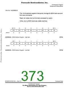
Development Support
Background Debug Mode
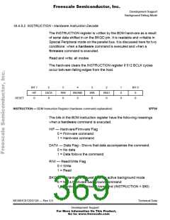
18.4.5.2 INSTRUCTION - Hardware Instruction Decode
The INSTRUCTION register is written by the BDM hardware as a result
of serial data shifted in on the BKGD pin. It is readable and writable in
Special Peripheral mode on the parallel bus. It is discussed here for two
conditions: when a hardware command is executed and when a
firmware command is executed.
Read and write: all modes
The hardware clears the INSTRUCTION register if 512 BCLK cycles
occur between falling edges from the host.
BIT 7
H/F
0
6
DATA
0
5
R/W
0
4
BKGND
0
3
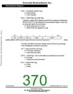
W/B
0
2
BD/U
0
1
0
0
BIT 0
0
0
RESET:
INSTRUCTION — BDM Instruction Register (hardware command explanation)
$FF00
The bits in the BDM instruction register have the following meanings
when a hardware command is executed.
H/F — Hardware/Firmware Flag
0 = Firmware command
1 = Hardware command
DATA — Data Flag - Shows that data accompanies the command.
0 = No data
1 = Data follows the command
R/W — Read/Write Flag
0 = Write
1 = Read
BKGND — Hardware request to enter active background mode
0 = Not a hardware background command
1 = Hardware background command (INSTRUCTION = $90)
MC68HC912DG128 — Rev 3.0
Technical Data
Development Support
For More Information On This Product,
Go to: www.freescale.com

 FREESCALE [ Freescale ]