Freescale Semiconductor, Inc.
Preliminary Electrical Specifications
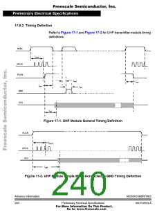
Control Timing
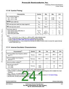
17.10 Control Timing
Characteristic
Bus operating frequency
Symbol
Min
Max
Unit
V
= 3.0 V ± 10%
f
32 k
32 k
4.0 M
2.0 M
Hz
DD
DD
BUS
V
= 2.0 V ± 10%
t
t
RESET pulse width low
1.5
1.5
—
—
—
RL
cyc
t
t
IRQ interrupt pulse width low (edge-triggered)
IRQ interrupt pulse period
ILHI
cyc
t
t
Note 4
ILIL
cyc
16-bit timer (Note 2)
Input capture pulse width (Note 3)
Input capture period
t
t
t
2
TH, TL
—
—
—
cyc
t
Note 4
t
TLTL
cyc
(1/f ) + 5
Input clock pulse width
t
, t
OP
ns
TCH TCL
Notes:
1. VDD = 1.8 V to 3.3 V, VSS = 0 Vdc, TA = –40oC to +85oC, unless otherwise noted
2. The 2-bit timer prescaler is the limiting factor in determining timer resolution.
3. Refer to Table 15-3. Mode, Edge, and Level Selection and supporting note.
4. The minimum period tTLTL or tILIL should not be less than the number of cycles it takes to execute the capture interrupt
service routine plus 2 tcyc
.
17.11 Internal Oscillator Characteristics
(1)
Symbol
Min
Typ
Max
Unit
Characteristic
Internal oscillator base frequency without
f
230.4
307.2
384.0
kHz
INTOSC
(2) (3)
trim
Internal oscillator base frequency
f
301.1
1
307.2
—
313.3
127
kHz
—
INTOSC(I)
(2) (3)
with trim
(4)
N
Internal oscillator multiplier
(5)
External clock option
f
128 k
128 k
—
—
16
8
MHz
3 V ± 10%
2 V ± 10%
EXTOSC
1. VDD = 1.8 V to 3.3 V, VSS = 0 Vdc, TA = –40oC to +85oC, unless otherwise noted
2. Internal oscillator is selectable through software for a maximum frequency. Actual frequency will be multiplier (N) x base
frequency.
3. f
= (f
/ 4) x (internal oscillator multiplier)
BUS
INTOSC
4. Multiplier must be chosen to limit the maximum bus frequency to the maximum listed in 17.10 Control Timing.
5. No more than 10% duty cycle deviation from 50%
MC68HC908RFRK2
MOTOROLA
AdvanceInformation
241
Preliminary Electrical Specifications
For More Information On This Product,
Go to: www.freescale.com

 FREESCALE [ Freescale ]