Freescale Semiconductor, Inc.
Preliminary Electrical Specifications
UHF Transmitter Module
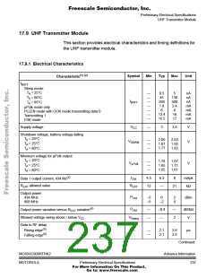
17.9 UHF Transmitter Module
This section provides electrical characteristics and timing definitions for
the UHF transmitter module.
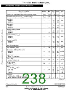
17.9.1 Electrical Characteristics
(1) (2)
Symbol
Min
Typ
Max
Unit
Characteristic
I
BATT
Sleep mode:
T = 25°C
—
—
—
—
—
—
—
0.5
45
260
1.8
6
5
nA
nA
nA
mA
mA
mA
mA
A
T = 60°C
130
500
2.4
9
16
17
A
I
BATT
T = 85°C
A
µPclk mode only
PLLEN mode with OOK mode transmitting data 0
Transmitting 1
FSK mode
13.4
15.5
V
Supply voltage
—
3
3.6
V
CC
Shutdown voltage, battery voltage falling
T = 20°C
A
—
—
—
2.00
1.87
1.77
2.03
1.92
1.82
V
V
SDWN
T = 25°C
A
T = 60°C
A
Minimum voltage for µPclk output
T = 20°C
A
—
—
—
1.78
1.65
1.55
1.87
1.71
1.61
V
V
µPclk
T = 25°C
A
T = 60°C
A
(3)
I
4.5
12
6.3
—
8
mApk
Data 1 output current, 434 Mz
Out
R
allowed value
R
21
kΩ
EXT
EXT
Output power
434 MHz
P
–3
–5
0
–2
2
0
dBm
Out
868 MHz
(4)
P
—
—
–0.4
—
—
2
dB/kΩ
Output power variation versus R
variation
Out
EXT
Allowed voltage swing above / below V
Data to RF delay
V
V
CC
Swing
(5)
Rising edge
—
—
—
2.1
2.1
2.8
2.8
µs
(6)
Falling edge
Continued
MC68HC908RFRK2
MOTOROLA
AdvanceInformation
237
Preliminary Electrical Specifications
For More Information On This Product,
Go to: www.freescale.com

 FREESCALE [ Freescale ]