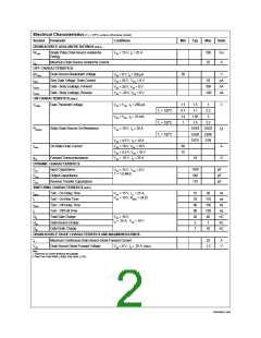
Electrical Characteristics (TC = 25°C unless otherwise noted)
Symbol
Parameter
Conditions
Min
Typ
Max
Units
DRAIN-SOURCE AVALANCHE RATINGS (Note 2)
WDSS
IAR
Single Pulse Drain-Source Avalanche
Energy
VDD = 15 V, ID = 25 A
100
25
mJ
A
Maximum Drain-Source Avalanche Current
OFF CHARACTERISTICS
Drain-Source Breakdown Voltage
30
V
BVDSS
IDSS
VGS = 0 V, ID = 250 µA
VDS = 24 V, VGS = 0 V
VGS = 20 V, VDS = 0 V
VGS = -20 V, VDS = 0 V
Zero Gate Voltage Drain Current
Gate - Body Leakage, Forward
Gate - Body Leakage, Reverse
10
µA
nA
nA
100
-100
IGSSF
IGSSR
ON CHARACTERISTICS (Note 2)
Gate Threshold Voltage
1.1
0.7
1.4
1
1.5
1.1
3
2.2
V
VGS(th)
VDS = VGS, ID = 250 µA
VDS = VGS, ID = 10 mA
VGS = 10 V, ID = 25 A
TJ = 125oC
TJ = 125oC
TJ = 125oC
1.85
1.5
3
2.2
Static Drain-Source On-Resistance
0.019
0.028
0.031
0.022
0.045
0.04
RDS(ON)
W
VGS = 4.5 V, ID = 10 A
VGS = 10 V, VDS = 10 V
VGS = 4.5 V, VDS = 10 V
VDS = 10 V, ID = 25 A
ID(on)
On-State Drain Current
60
15
A
S
gFS
Forward Transconductance
18
DYNAMIC CHARACTERISTICS
Input Capacitance
1100
540
pF
pF
pF
Ciss
Coss
Crss
VDS = 15 V, VGS = 0 V,
f = 1.0 MHz
Output Capacitance
Reverse Transfer Capacitance
175
SWITCHING CHARACTERISTICS (Note 2)
tD(on)
tr
tD(off)
tf
Turn - On Delay Time
Turn - On Rise Time
Turn - Off Delay Time
Turn - Off Fall Time
Total Gate Charge
VDD = 15 V, ID = 25 A,
VGS = 10 V, RGEN = 24 W
15
70
90
80
28
5
30
110
150
130
40
ns
ns
ns
ns
Qg
Qgs
Qgd
VDS = 10 V,
ID = 25 A, VGS = 10 V
nC
nC
nC
Gate-Source Charge
Gate-Drain Charge
7
7
10
DRAIN-SOURCE DIODE CHARACTERISTICS AND MAXIMUM RATINGS
Maximum Continuous Drain-Source Diode Forward Current
Drain-Source Diode Forward Voltage
25
A
V
IS
1.3
VSD
VGS = 0 V, IS = 25 A (Note 2)
Note:
1. Maximum DC current limited by the package.
2. Pulse Test: Pulse Width < 300µs, Duty Cycle < 2.0%.
NDP603AL.SAM

 FAIRCHILD [ FAIRCHILD SEMICONDUCTOR ]