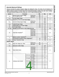
Electrical Characteristics
TA=25°C unless otherwise specified.
Specifications
Symbol
Parameter
Test Conditions
Unit
Min.
Typ.
Max.
MOSFET Section
600
500
ID=200μA, TA=25°C
ID=200μA, TA=125°C
ID=200μA, TA=25°C
ID=200μA, TA=125°C
VGS=10V, ID=5.5A
VGS=10V, ID=5.0A
VGS=10V, ID=4.0A
VGS=10V, ID=3.0A
FSFR2100
All Others
650
Drain-to-Source
BVDSS
V
Breakdown Voltage
On-State Resistance
540
0.32
0.53
0.74
0.77
1.00
FSFR2100
FSFR2000
FSFR1900
FSFR1800
FSFR1700
0.38
0.67
0.85
0.95
1.25
RDS(ON)
Ω
VGS=10V, ID=2.0A
VGS=0V, IDiode=11.0A,
dIDiode/dt=100A/μs
FSFR2100
FSFR2000
FSFR1900
FSFR1800
FSFR1700
120
125
140
160
160
VGS=0V, IDiode=9.5A,
dIDiode/dt=100A/μs
Body Diode Reverse
Recovery Time(5)
VGS=0V, IDiode=8.0A,
trr
ns
dIDiode/dt=100A/μs
VGS=0V, IDiode=7.0A,
dIDiode/dt=100A/μs
VGS=0V, IDiode=6.0A,
dIDiode/dt=100A/μs
Supply Section
ILK
Offset Supply Leakage Current
Quiescent HVCC Supply Current
H-VCC=VCTR=600V/500V
(HVCCUV+) - 0.1V
50
120
200
9
μA
μA
IQHVCC
IQLVCC
50
100
6
Quiescent LVCC Supply Current
(LVCCUV+) - 0.1V
μA
fOSC=100KHz, VCON > 0.6V
No switching, VCON < 0.4V
fOSC=100KHz, VCON > 0.6V
No switching, VCON < 0.4V
mA
μA
Operating HVCC Supply Current
(RMS Value)
IOHVCC
IOLVCC
100
7
200
11
mA
mA
Operating LVCC Supply Current
(RMS Value)
2
4
UVLO Section
LVCCUV+ LVCC Supply Under-Voltage Positive Going Threshold (LVCC Start)
LVCCUV- LVCC Supply Under-Voltage Negative Going Threshold (LVCC Stop)
LVCCUVH LVCC Supply Under-Voltage Hysteresis
13.0
10.2
14.5
11.3
3.2
16.0
12.4
V
V
V
V
V
V
HVCCUV+ HVCC Supply Under-Voltage Positive Going Threshold (HVCC Start)
8.2
7.8
9.2
10.2
9.6
HVCC Supply Under-Voltage Negative Going Threshold (HVCC Stop)
HVCCUV-
8.7
HVCCUVH HVCC Supply Under-Voltage Hysteresis
0.5
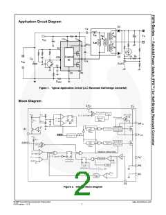
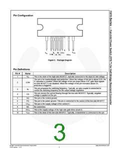
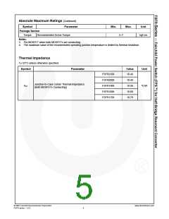
© 2007 Fairchild Semiconductor Corporation
FSFR series • 1.0.3
www.fairchildsemi.com
6

 FAIRCHILD [ FAIRCHILD SEMICONDUCTOR ]