Functional Description
Gain
1.8
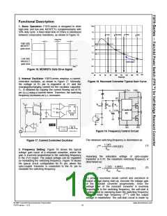
1. Basic Operation: FSFR-series is designed to drive
high-side and low-side MOSFETs complementarily with
50% duty cycle. A fixed dead time of 350ns is introduced
between consecutive transitions, as shown in Figure 16.
f max
f min
f normal
f ISS
1.6
1.4
1.2
1.0
0.8
0.6
Dead time
High side
MOSFET
gate drive
Low side
MOSFET
gate drve
Soft-start
time
Figure 16. MOSFETs Gate Drive Signal
150
60
70
80
90
100
110
freq (kHz)
120
130
140
2. Internal Oscillator: FSFR-series employs a current-
controlled oscillator, as shown in Figure 17. Internally,
the voltage of RT pin is regulated at 2V and the
charging/discharging current for the oscillator capacitor,
CT, is obtained by copying the current flowing out of RT
pin (ICTC) using a current mirror. Therefore, the switching
frequency increases as ICTC increases.
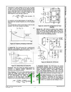
Figure 18. Resonant Converter Typical Gain Curve
LVcc
VDL
RT
Rss
CON
Rmax
Rmin
Css
Control
IC
SG
PG
Figure 19. Frequency Control Circuit
The minimum switching frequency is determined as:
Figure 17. Current Controlled Oscillator
5.2kΩ
Rmin
f min
=
×100(kHz)
(1)
3. Frequency Setting: Figure 18 shows the typical
voltage gain curve of a resonant converter, where the
gain is inversely proportional to the switching frequency
in the ZVS region. The output voltage can be regulated
by modulating the switching frequency. Figure 19 shows
the typical circuit configuration for RT pin, where the
opto-coupler transistor is connected to the RT pin to
modulate the switching frequency.
Assuming the saturation voltage of opto-coupler
transistor is 0.2V, the maximum switching frequency is
determined as:
5.2kΩ 4.68kΩ
f max = (
+
)×100(kHz)
(2)
Rmin
Rmax
To prevent excessive inrush current and overshoot of
output voltage during start-up, increase the voltage gain
of the resonant converter progressively. Since the
voltage gain of the resonant converter is inversely
proportional to the switching frequency, the soft-start is
implemented by sweeping down the switching frequency
from an initial high frequency (fISS) until the output
voltage is established. The soft-start circuit is made by
© 2007 Fairchild Semiconductor Corporation
FSFR series • 1.0.3
www.fairchildsemi.com
10

 FAIRCHILD [ FAIRCHILD SEMICONDUCTOR ]