FSCQ-SERIES
The minimum average of the current supplied from the AC is
given by
Functional Description
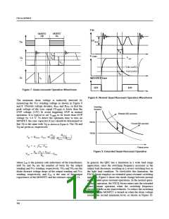
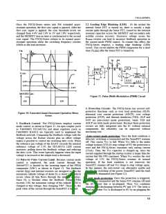
1. Startup: Figure 4 shows the typical startup circuit and
the transformer auxiliary winding for the FSCQ-Series.
Before the FSCQ-Series begins switching, it consumes only
startup current (typically 25uA). The current supplied from
min
2 ⋅ Vac
Vstart
⎛
⎜
⎝
⎞
avg
1
Rstr
----------------------------- -------------- ---------
Isup
=
–
⋅
⎟
⎠
π
2
the AC line charges the external capacitor (C ) that is
a1
connected to the Vcc pin. When Vcc reaches the start voltage
of 15V (VSTART), the FSCQ-Series begins switching, and its
current consumption increases to I . Then, the FSCQ-
OP
min
where V
ac
is the minimum input voltage, V
is the
start
FSCQ-Series start voltage (15V), and R is the startup
str
resistor. The startup resistor should be chosen so that I
is larger than the maximum startup current (50uA).
avg
sup
Series continues its normal switching operation and the
power required for the FSCQ-Series is supplied from the
transformer auxiliary winding, unless Vcc drops below the
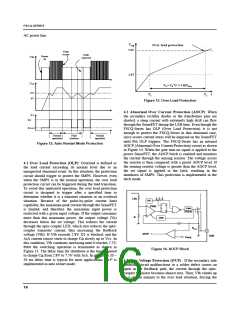
stop voltage of 9V (VSTOP). To guarantee the stable operation
of the control IC, Vcc has under voltage lockout (UVLO)
with 6V hysteresis. Figure 5 shows the relationship between
the operating supply current of the FSCQ-Series and the
supply voltage (Vcc).
Once the resistor value is determined, the maximum loss in
the startup resistor is obtained as
2
2
max
(V max) + Vstart
2 2 ⋅ Vstart ⋅ Vac
⎛
⎞
⎟
⎠
1
ac
--------- -------------------------------------------------- -----------------------------------------------------
Loss =
⋅
–
⎜
⎝
Rstr
2
π
max
where V
ac
is the maximum input voltage. The startup
resistor should have properly-rated dissipation wattage.
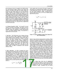
2. Synchronization: The FSCQ-Series employs a quasi-
resonant switching technique to minimize the switching noise
and loss. In this technique, a capacitor (Cr) is added between
the MOSFET drain and the source as shown in Figure 6. The
basic waveforms of the quasi-resonant converter are shown in
Figure 7. The external capacitor lowers the rising slope of the
drain voltage to reduce the EMI caused when the MOSFET
turns off. To minimize the MOSFET’s switching loss, the
MOSFET should be turned on when the drain voltage reaches
its minimum value as shown in Figure 7.
CDC
1N4007
Isup
AC line
min
max
(Vac
- Vac
)
Rstr
Da
Vcc
FSCQ-Series
Ca2
Ca1
+
VDC
-
Np
CDC
Ns
Lm
Vo
Figure 4. Startup circuit
Drain
+
Vds
-
Cr
Ids
Sync
Icc
IOP Value
FSCQ0565RT : 4mA (Typ.)
FSCQ0765RT : 4mA (Typ.)
FSCQ0965RT : 6mA (Typ.)
FSCQ1265RT : 6mA (Typ.)
FSCQ1465RT : 7mA (Typ.)
FSCQ1565RT : 7mA (Typ.)
FSCQ1565RP : 7mA (Typ.)
GND
Da
Vco
Vcc
Rcc
Ca2
Na
Ca1
DSY
IOP
RSY1
Power Up
Power Down
CSY
RSY2
ISTART
Vcc
Vstop=9V
Vstart=15V
Vz
Figure 6. Synchronization Circuit
Figure 5. Relationship Between Operating Supply Current
and Vcc Voltage
13

 FAIRCHILD [ FAIRCHILD SEMICONDUCTOR ]