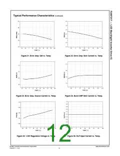
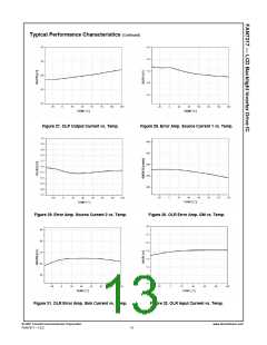
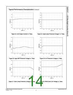
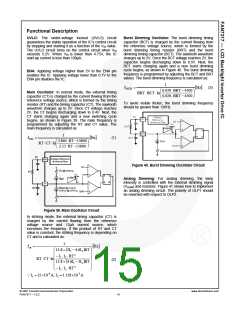
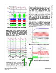
Burst Dimming: Lamp intensity is controlled with the
BDIM signal over a wide range. When BDIM voltage is
lower than BCT voltage, the lamp current is turned on;
so, 0V on BDIM commands full brightness. The duty
cycle of the PWM pulse determines the lamp brightness.
The lamp intensity is inversely proportional to BDIM
voltage. As BDIM voltage increases, the lamp intensity
decreases. Figure 43 shows the lamp current waveform
vs. DIM in negative analog dimming mode.
T1
R1
R2
Full-
bridge
output
RS2
R2
R1
RS2
2V
T2
VBDIM
BCT
0.5V
0
RS1
CMP
0.5V
0
0
iLamp
RS1
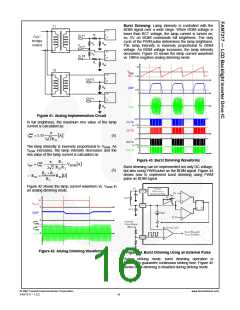
Figure 41. Analog Implementation Circuit
VIN(V)
OUTA
In full brightness, the maximum rms value of the lamp
current is calculated as:
VIN-7(V)
7V
OUTB
π
0
max
rms
i
=1.35
[A
]
(4)
V
IN(V)
2 2RS1
OUTC
V
IN-7(V)
7V
The lamp intensity is inversely proportional to VADIM. As
VADIM increases, the lamp intensity decreases and the
rms value of the lamp current is calculated as:
OUTD
0
Figure 43. Burst Dimming Waveforms
R1
π
max
rms
irms = i
Q RS2
−
VADIM
[A]
Burst dimming can be implemented not only DC voltage,
but also using PWM pulse as the BDIM signal. Figure 44
shows how to implement burst dimming using PWM
pulse as BDIM signal.
RS2R2
2 2
(5)
R1 + R2
=
RS1
[ ]
Ω
R2
Figure 42 shows the lamp current waveform vs. VADIM in
an analog dimming mode.
tdch
tch
b
b
max
Lamp
i
min
Lamp
i
Figure 42. Analog Dimming Waveforms
Figure 44. Burst Dimming Using an External Pulse
During striking mode, burst dimming operation is
disabled to guarantee continuous striking time. Figure 45
shows burst dimming is disabled during striking mode.
© 2007 Fairchild Semiconductor Corporation
FAN7317 • 1.0.2
www.fairchildsemi.com
16

 FAIRCHILD [ FAIRCHILD SEMICONDUCTOR ]