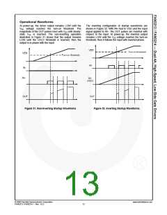
Operational Waveforms
At power-up, the driver output remains LOW until the
VDD voltage reaches the turn-on threshold. The
magnitude of the OUT pulses rises with VDD until steady-
state VDD is reached. The non-inverting operation
illustrated in Figure 31 shows that the output remains
LOW until the UVLO threshold is reached, then the
output is in-phase with the input.
The inverting configuration of startup waveforms are
shown in Figure 32. With IN+ tied to VDD and the input
signal applied to IN–, the OUT pulses are inverted with
respect to the input. At power-up, the inverted output
remains LOW until the VDD voltage reaches the turn-on
threshold, then it follows the input with inverted phase.
Figure 31. Non-Inverting Startup Waveforms
Figure 32. Inverting Startup Waveforms
© 2008 Fairchild Semiconductor Corporation
FAN3213 / FAN3214 • Rev. 1.0.2
www.fairchildsemi.com
13

 FAIRCHILD [ FAIRCHILD SEMICONDUCTOR ]