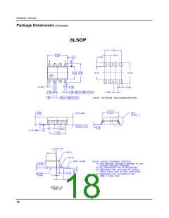
FSDH321, FSDL321
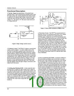
Typical application circuit
1. PC Auxiliary Power Circuit (10W Output Power)
L201
10uH
D201
T1
SB360
5V
(+/-5%)
2A
140~ 375
VDC
EE1625
10
7
1
2
INPUT
C201
1000uF
16V
C 203
470uF
16V
C101
10nF
630V
R 102
100kΩ
1W
R 101
680kΩ
1W
D101
UF 4007
3
D102
R 103
10Ω
1N 4937
M Vcc
4
5
Vstr
IC101
FSDx321
C102
47uF
50V
Drain
Vcc
6,7,8
2
D103
3
R104
10Ω
Vfb
1N 4937
5
6
ZD1
19V
C104
22nF
GND
1
ZD2
19V
R202
330Ω
PC301
H11A817A
R203
2kΩ
C103
R201
1kΩ
10uF
50V
C202
100nF
C301
2.2nF
R204
2kΩ
IC201
KA431
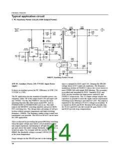
10W PC Auxiliary Power Circuit
10W PC Auxiliary Power, 150~375VDC Input Power
supply:
tance is clamped by R102 and C101, keeping the DRAIN
voltage below 650 V under all conditions. The frequency
modulation feature of FSDH321 allows the circuit shown to
meet CISPR2AB with simple EMI filtering. The secondary
is rectified and smoothed by D201. Similarly D102 and
D103 are also rectifiers for main power control IC and
FSDH321 respectively. The 5V output voltage require two
capacitors in parallel to meet the ripple current requirement.
Switching noise filtering is provided by L201. The output is
regulated by the reference (TL431) voltage in secondary. It
is sensed via R203 and R204. Resistor R201 provides bias
for TL431 and R202 sets the overall DC gain. R202, C202
and R203 provide loop compensation.
It shows an auxiliary power for PC. Efficiency at 10W, 150/
375VDC is ≥70%.
The PC application has the standard of standby power con-
sumption, under 1W at the output load 0.5W and input volt-
age 230VAC. For this the FSDH321 also has the burst
operating function like other green mode FPS’ such as
FSDM0265RN or FSDM0365RN and so on. This skill
reduces the MOSFET switching numbers and power MOS-
FET switching loss. This design takes advantage of self pro-
tection without external components and high switching
frequency, 100kHz. The frequency makes using a small size
transformer core possible. The EE16 or EE1625 can be used
for 10W application.
This is achieved by preventing the green FPS from switching
when the input voltage goes below a level needed to main-
tain output regulation, and keeping it off until the input volt-
age goes above the under-voltage threshold, when the AC is
turned on again. For example with the resistor, R101,
680kΩ, the threshold voltage is around 150VAC(210VDC)
at the room temperature.
Surge voltages on the DRAIN pin due to the leakage induc-
14

 FAIRCHILD [ FAIRCHILD SEMICONDUCTOR ]