FSDH321, FSDL321
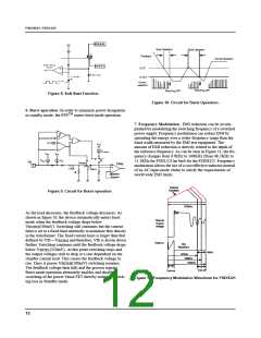
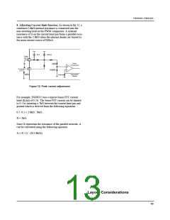
8. Adjusting Current limit function: As shown in fig 12, a
combined 2.8kΩ internal resistance is connected into the
non-inverting lead on the PWM comparator. A external
resistance of A on the current limit pin forms a parallel resis-
tance with the 2.8kΩ when the internal diodes are biased by
the main current source of 900uA.
5uA
900uA
Feed
Back
3
4
PWM
comparator
2KΩ
0.8KΩ
Current
Limit
AKΩ
SenseFET
Sense
Rsense
Figure 12. Peak current adjustment
For example, FSDH321 has a typical Sense FET current
limit (I
) of 0.7A. The Sense FET current can be limited
LIM
to 0.5 by inserting a 7kΩ between the current limit pin and
ground which is derived from the following equations:
0.7: 0.5 = 2.8kΩ : XkΩ ,
X = 2kΩ,
Since X represents the resistance of the parallel network, A
can be calculated using the following equation:
A = X / (1 - (X/2.8kΩ))
Layout Considerations
13

 FAIRCHILD [ FAIRCHILD SEMICONDUCTOR ]