FSDH321, FSDL321
D R A IN
5 V
Burst Operation
Burst Operation
Feedback
Normal Operation
S W IT C H
O F F
G N D
0.5V
0.5V
R sen se
I_o ver
0.3V
0.35V
Current
waveform
Switching OFF
Switching OFF
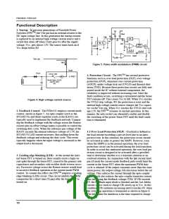
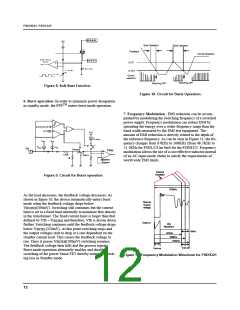
Figure 8. Soft Start Function
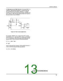
Figure 10. Circuit for Burst Operation
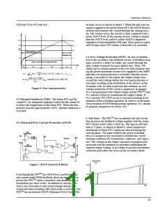
6. Burst operation :In order to minimize power dissipation
in standby mode, the FPSTM enters burst mode operation.
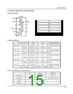
7. Frequency Modulation : EMI reduction can be accom-
plished by modulating the switching frequency of a switched
power supply. Frequency modulation can reduce EMI by
spreading the energy over a wider frequency range than the
band width measured by the EMI test equipment. The
amount of EMI reduction is directly related to the depth of
the reference frequency. As can be seen in Figure 11, the fre-
quency changes from 97KHz to 100KHz (from 48.5KHz to
51.5KHz for FSDL321)in 4mS for the FSDH321. Frequency
modulation allows the use of a cost effective inductor instead
of an AC input mode choke to satisfy the requirements of
world wide EMI limits.
+
-
0.35V/0.5V
0.3/0.5V
00..55VV
Vcc
IB_PEAK
Vcc
Vcc
Idelay
IFB
FB
Normal
PWM
3
2.5R
Burst
R
MOSFET
Current
Internal
Oscillator
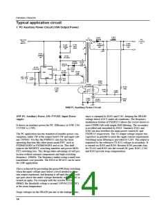
Figure 9. Circuit for Burst operation
103kHz
As the load decreases, the feedback voltage decreases. As
shown in figure 10, the device automatically enters burst
mode when the feedback voltage drops below
Drain to
Source
voltage
V
(500mV). Switching still continues but the current
BURH
limit is set to a fixed limit internally to minimize flux density
in the transformer. The fixed current limit is larger than that
defined by Vfb = V
and therefore, Vfb is driven down
BURH
Drain to
Vds
further. Switching continues until the feedback voltage drops
Waveform
below V
(350mV). At this point switching stops and
BURL
6kHz
97kHz
the output voltages start to drop at a rate dependent on the
standby current load. This causes the feedback voltage to
100kHz
103kHz
rise. Once it passes V
(500mV) switching resumes.
BURH
The feedback voltage then falls and the process repeats.
Burst mode operation alternately enables and disables
switching of the power Sense FET thereby reducing switch-
ing loss in Standby mode.
Turn-off
Turn-on
Figure 11. Frequency Modulation Waveform for FSDH321
12

 FAIRCHILD [ FAIRCHILD SEMICONDUCTOR ]