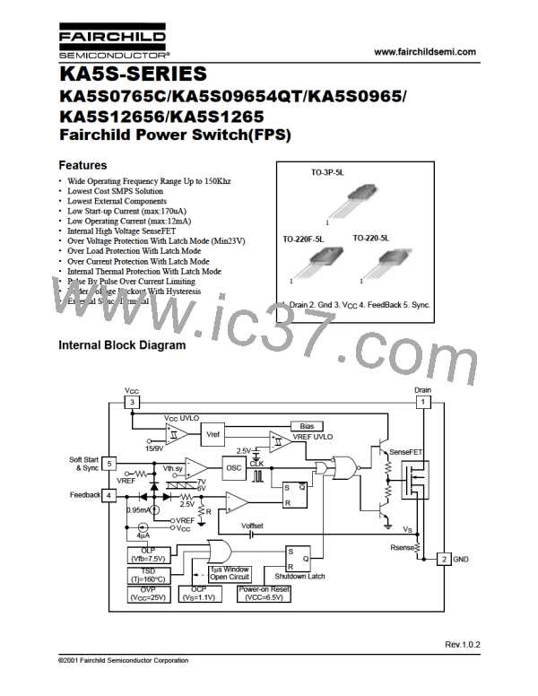
KA5S-SERIES KA5S0765C/KA5S09654QT/KA5S0965/KA5S12656/KA5S1265
Electrical Characteristics (CONTROL Part)
(V =16V, Tamb = 25°C unless otherwise specified)
CC
Parameter
UVLO SECTION
Symbol
Conditions
Min. Typ. Max. Unit
Start Threshold Voltage
StopThreshold Voltage
OSCILLATOR SECTION
Initial Frequency
V
V
V
=GND
14
8
15
9
16
10
V
V
START
FB
FB
V
=GND
STOP
F
-
18
0
20
1
22
3
kHz
%
OSC
Voltage Stability
F
12V ≤ V
≤ 23V
CC
STABLE
Temperature Stability (Note2)
Maximum Duty Cycle
∆F
-25°C ≤ Τa≤ 85°C
0
±5
95
-
±10
98
0
%
OSC
MAX
D
-
-
92
-
%
Minimum Duty Cycle
D
MIN
%
FEEDBACK SECTION
Feedback Source Current
Shutdown Feedback Voltage
Shutdown Delay Current
SYNC. & SOFTSTART SECTION
Softstart Voltage
I
V
V
V
=GND
≥ 6.9V
=5V
0.7
6.9
3.0
0.9
7.5
4.0
1.1
8.1
5.0
mA
V
FB
FB
FB
FB
V
SD
I
µA
DELAY
V
V
V
V
V
=2V
=0V
4.7
5.0
5.3
V
mA
V
SS
FB
SS
CC
CC
Softstart Current
I
0.75 0.95 1.15
SS
Sync High Threshold Voltage(Note3)
Sync Low Threshold Voltage(Note3)
V
=16V , V =5V
FB
-
-
7.0
6.0
-
-
SYNCH
V
=16V , V =5V
FB
V
SYNCL
CURRENT LIMIT(SELF-PROTECTION)SECTION
KA5S0765C
KA5S09654QT
KA5S0965
3.52
3.52
5.28
5.28
7.04
4.0
4.0
6.0
6.0
8.0
4.48
4.48
6.72
6.72
8.96
Peak Current Limit (Note4)
IOVER
A
KA5S12656
KA5S1265
PROTECTION SECTION
Over Voltage Protcetion
V
V
V
≥ 24V
CC
23
0.9
140
25
1.0
160
28
1.1
-
V
V
OVP
Over Current Latch voltage(Note3)
Thermal Shutdown Tempature(Note2)
TOTAL DEVICE SECTION
Start Up Current
-
-
OCL
TSD
°C
I
V
V
V
V
=GND, V =14V
CC
-
-
0.1
7
0.17
12
mA
mA
START
FB
FB
FB
FB
I
=GND, V =16V
CC
OP
OP(MIN)
Operating Supply Current(Note1)
I
=GND, V =12V
CC
I
=GND, V =30V
CC
OP(MAX)
Note:
1. These parameters is the Current Flowing in the Control IC.
2. These parameters, although guaranteed, are not 100% tested in production
3. These parameters, although guaranteed, are tested in EDS(wafer test) process
4. These parameters are indicated Inductor Current.
8

 FAIRCHILD [ FAIRCHILD SEMICONDUCTOR ]