XRT86L30
SINGLE T1/E1/J1 FRAMER/LIU COMBO
REV. 1.0.1
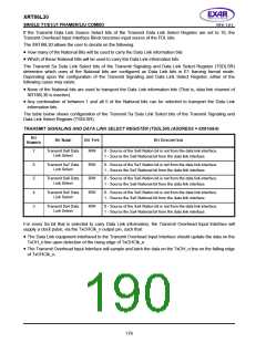
If the Receive Data Link Source Select bits of the Receive Data Link Select Register are set to 10, the Receive
Overhead Output Interface Block becomes Output source of the FDL bits.
The XRT86L30 allows the user to select bandwidth of the Facility Data Link Channel in ESF framing format
mode. The FDL can be either a 4KHz or 2KHz data link channel. The Receive Data Link Bandwidth Select bits
of the Receive Data Link Select Register (RDLSR) determine the bandwidth of FDL channel in ESF framing
format mode.
The table below shows configuration of the Receive Data Link Bandwidth Select bits of the Receive Data Link
Select Register (TDLSR).
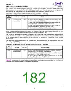
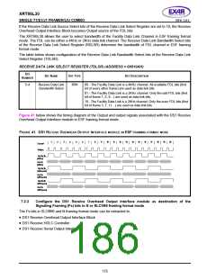
RECEIVE DATA LINK SELECT REGISTER (TDLSR) (ADDRESS = 0X010AH)
B
IT
B
IT
N
AME
B
IT
TYPE
BIT DESCRIPTION
N
UMBER
5-4
Receive Data Link
Bandwidth Select
R/W
00 - The Facility Data Link is a 4KHz channel. All available FDL bits (first
bit of every other frame) are used as data link bits.
01 - The Facility Data Link is a 2KHz channel. Only the odd FDL bits (first
bit of frame 1, 5, 9…) are used as data link bits.
10 - The Facility Data Link is a 2KHz channel. Only the even FDL bits (first
bit of frame 3, 7, 11…) are used as data link bits.
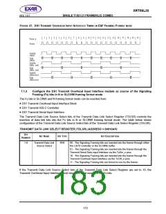
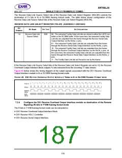
Figure 41 below shows the timing diagram of the Output and output signals associated with the DS1 Receive
Overhead Output Interface module in ESF framing format mode.
FIGURE 41. DS1 RECEIVE OVERHEAD OUTPUT INTERFACE MODULE IN ESF FRAMING FORMAT MODE
1
2
3
4
5
6
7
8
9
10
11
12
13
14
15
16
17
18
19
20
Frame#
RxSync
RxOhClk
(4KHz)
RxOh
(4KHz)
RxOhClk
(2KHz,odd)
RxOh
(2KHz,odd)
RxOhClk
(2KHz,even)
RxOh
(2KHz,even)
7.2.3
Configure the DS1 Receive Overhead Output Interface module as destination of the
Signaling Framing (Fs) bits in N or SLC®96 framing format mode
The Fs bits in SLC®96 and N framing format mode can be extracted to:
•
•
•
DS1 Receive Overhead Output Interface Block
DS1 Receive HDLC Controller
DS1 Receive Serial Output Interface.
175

 EXAR [ EXAR CORPORATION ]