XRT86L30
REV. 1.0.1
SINGLE T1/E1/J1 FRAMER/LIU COMBO
7.2.1
Description of the DS1 Receive Overhead Output Interface Block
The DS1 Receive Overhead Output Interface Block allows an external device to be the consumer of the
Facility Data Link (FDL) bits in ESF framing format mode, Signaling Framing (Fs) bits in the SLC96 and N
framing format mode and Remote Signaling (R) bit in T1DM framing format mode This interface provides
interface signals and required interface timing to shift out proper data link information at proper time.
The Receive Overhead Output Interface for a given Framer consists of two signals.
•
•
RxOHClk_n: The Receive Overhead Output Interface Clock Output signal
RxOH_n: The Receive Overhead Output Interface Output signal.
The Receive Overhead Output Interface Clock Output pin (RxOHCLK_n) generates a rising clock edge for
each data link bit position according to configuration of the framer. The data link bits extracted from the
incoming T1 frames are outputted from the Receive Overhead Output Interface Output pin (RxOH_n) at the
rising edge of RxOHClk_n. The Data Link equipment should sample and latch the data link bits at the falling
edge of RxOHClk_n.
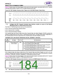
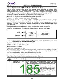
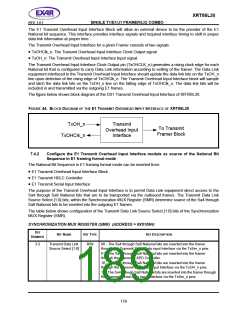
The figure below shows block diagram of the Receive Overhead Output Interface of XRT86L30.
FIGURE 40. BLOCK
D
IAGRAM OF THE DS1 RECEIVE
O
VERHEAD
O
UTPUT
INTERFACE OF XRT86L30
RxOH_n
RxOHClk_n
Receive
Overhead Output
Interface
From Receive
Framer Block
7.2.2
Configure the DS1 Receive Overhead Output Interface module as destination of the Facility
Data Link (FDL) bits in ESF framing format mode
The FDL bits in ESF framing format mode can be extracted to:
•
•
•
DS1 Receive Overhead Output Interface Block
DS1 Receive HDLC Controller
DS1 Receive Serial Output Interface.
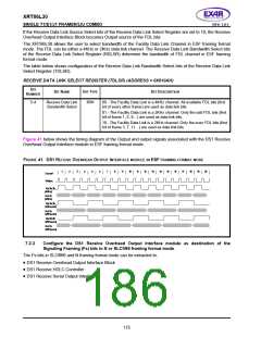
The Receive Data Link Source Select bits of the Receive Data Link Select Register (RDLSR) controls the
extraction of FDL bits in ESF framing format mode. The table below shows configuration of the Receive Data
Link Source Select bits of the Receive Data Link Select Register (RDLSR).
RECEIVE DATA LINK SELECT REGISTER (TDLSR) (ADDRESS = 0X010AH)
B
IT
B
IT
N
AME
B
IT
TYPE
BIT DESCRIPTION
N
UMBER
1-0
Receive Data Link
Destination Select
R/W
00 - The extracted Facility Data Link bits are stored in either the LAPD con-
troller or the SLC®96 buffer. At the same time, the extracted Facility Data
Link bits are outputted from the framer through the Receive Serial Data
Output Interface via the RxSer_n pins.
01 - The extracted Facility Data Link bits are outputted from the framer
through the Receive Serial Data Output Interface via the RxSer_n pins.
10 - The extracted Facility Data Link bits are outputted from the framer
through the Receive Overhead Output Interface via the RxOH_n pins. At
the same time, the extracted Facility Data Link bits are outputted from the
framer through the Receive Serial Data Output Interface via the RxSer_n
pins.
11 - The Facility Data Link bits are forced to one by the framer.
174

 EXAR [ EXAR CORPORATION ]