XRT86L30
SINGLE T1/E1/J1 FRAMER/LIU COMBO
4.10 Overhead Interface
REV. 1.0.1
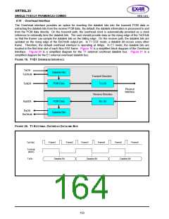
The Overhead interface provides an option for inserting the datalink bits into the transmit PCM data or
extracting the datalink bits from the receive PCM data. By default, the datalink information is processed to and
from the PCM data directly. On the transmit path, the overhead clock is automatically provided as a clock
reference to externally time the datalink bits. The user should provide data on the rising edge of the TxOHclk
so that the framer can sample the datalink bits on the falling edge. On the receive path, the datalink bits are
updated on the rising edge of the RxOHclk output pin. In T1 ESF mode, a datalink bit occurs every other
frame. Therefore, the default overhead interface is operating at 4kbps. In E1 mode, the datalink bits are
located in the first time slot of each Non-FAS frame. Figure 19 is a simplified block diagram of the Overhead
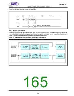
Interface. Figure 20 is a simplified diagram for the T1 external overhead datalink bus. Figure 21 is a
simplified diagram for the E1 external overhead datalink bus.
F
IGURE 19. T1/E1 OVERHEAD INTERFACE
TxOH
Datalink Bits
PCM Data
TxOHclk
Transmit Direction
Tx LIU
TxSER
RxSER
Physical
Interface
Receive Direction
Rx LIU
PCM Data
RxOH
Datalink Bits
RxOHclk
F
IGURE 20. T1 EXTERNAL OVERHEAD DATALINK BUS
Frame1
Frame2
Frame3
Frame4
Frame5
Frame6
TxSYNC
TxOHclk
(4kHz)
TxOH
Datalink Bit
Datalink Bit
Datalink Bit
153

 EXAR [ EXAR CORPORATION ]