XRT86L30
SINGLE T1/E1/J1 FRAMER/LIU COMBO
REV. 1.0.1
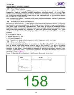
4.9
Robbed Bit Signaling/CAS Signaling
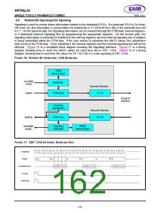
Signaling is used to convey status information relative to the individual DS-0’s. If a particular DS-0 is On Hook,
Off Hook, etc. this information is carried within the robbed bits in T1 (SF/ESF/SLC-96) or the sixteenth time slot
in E1. On the transmit path, the Signaling information can be inserted through the PCM data, internal registers,
or a dedicated external Signaling Bus by programming the appropriate registers. On the receive path, the
signaling information is extracted (if enabled) to the internal registers and the external signaling bus in addition
to being embedded within the PCM data. If the user wishes to substitute the ABCD values, the substitution
only occurs in the PCM data. Once substituted, the internal registers and the external signaling bus will not be
affected. Figure 16 is a simplified block diagram showing the Signaling Interface. Figure 17 is a timing
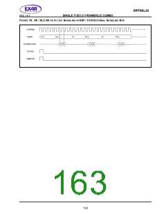
diagram showing how to insert the ABCD values for each time slot in ESF / CAS. Figure 18 is a timing
diagram showing how to insert the AB values for SF / SLC-96 or 4-code signaling in ESF / CAS.
F
IGURE 16. ROBBED
B
IT
S
IGNALING / CAS SIGNALING
TSCR
Internal Reg's
TxCHN0/
TxSIG
RBS/CAS
PCM Data
Transmit Direction
Tx LIU
TxSER
Physical
Interface
Signaling
Substitution
Receive Direction
Rx LIU
PCM Data
Signaling
RxSER
RSAR
RxCHN0/
RxSIG
Extraction
Internal Reg's
F
IGURE 17. ESF / CAS EXTERNAL SIGNALING BUS
TxSERclk
TxSER
TxCHN0/TxSIG
TxSYNC
TS 2
TS 3
F
TS 1
A
B
A
B
A
B
C
D
C
D
C
D
TxMSYNC
151

 EXAR [ EXAR CORPORATION ]