XR16L2552
2.25V TO 5.5V DUART WITH 16-BYTE FIFO
xr
REV. 1.1.1
AFR[0]: Concurrent Write Mode
When this bit is set, the CPU can write concurrently to the same register in both UARTs. This function is
intended to reduce the dual UART initialization time. It can be used by the CPU when both channels are
initialized to the same state. The external CPU can set or clear this bit by accessing either register set. When
this bit is set, the channel select pin still selects the channel to be accessed during read operations. The user
should ensure that LCR Bit-7 of both channels are in the same state before executing a concurrent write to the
registers at address 0, 1, or 2.
• Logic 0 = No concurrent write (default).
• Logic 1 = Register set A and B are written concurrently with a single external CPU I/O write operation.
AFR[2:1]: MF# Output Select
These bits select a signal function for output on the MF# A/B pins. These signal function are described as:
OP2#, BAUDOUT#, or RXRDY#. Only one signal function can be selected at a time.
BIT-2
BIT-1
MF# FUNCTION
0
0
1
1
0
1
0
1
OP2# (default)
BAUDOUT#
RXRDY#
Reserved
AFR[7:3]: Reserved
All are initialized to logic 0.
4.14 Device Identification Register (DVID) - Read Only
This register contains the device ID (0x02 for XR16L2552). Prior to reading this register, DLL and DLM should
be set to 0x00.
4.15 Device Revision Register (DREV) - Read Only
This register contains the device revision information. For example, 0x01 means revision A. Prior to reading
this register, DLL and DLM should be set to 0x00.
4.16 Enhanced Feature Register (EFR)
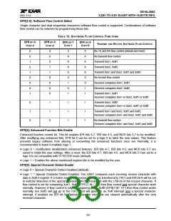
Enhanced features are enabled or disabled using this register. Bit 0-3 provide single or dual consecutive
character software flow control selection (see Table 12). When the Xon1 and Xon2 and Xoff1 and Xoff2 modes
are selected, the double 8-bit words are concatenated into two sequential characters. Caution: note that
whenever changing the TX or RX flow control bits, always reset all bits back to logic 0 (disable) before
programming a new setting.
32

 EXAR [ EXAR CORPORATION ]