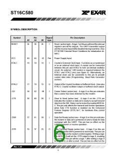
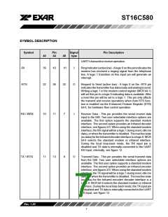
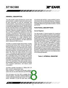
ST16C580
FIFO Operation
Hardware Flow Control
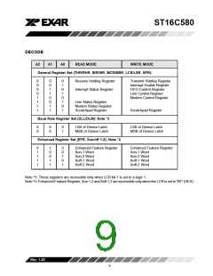
The 16 byte transmit and receive data FIFO’s are
enabled by the FIFO Control Register (FCR) bit-0.
With 16C550 devices, the user can set the receive
trigger level but not the transmit trigger level. The 580
provides independent trigger levels for both receiver
and transmitter. To remain compatible with
ST16C550, the transmit interrupt trigger level is set to
1 following a reset. It should be noted that the user can
set the transmit trigger levels by writing to the FCR
register, but activation will not take place until EFR bit-
4 is set to a logic 1. The receiver FIFO section includes
a time-out function to ensure data is delivered to the
external CPU. An interrupt is generated whenever the
Receive Holding Register (RHR) has not been read
following the loading of a character or the receive
triggerlevelhasnotbeenreached. (seehardwareflow
control for a description of this timing).
When automatic hardware flow control is enabled, the
580monitorsthe-CTSpinforaremotebufferoverflow
indication and controls the -RTS pin for local buffer
overflows. Automatic hardware flow control is se-
lected by setting bits 6 (RTS) and 7 (CTS) of the EFR
register to a logic 1. If -CTS transitions from a logic 0
to a logic 1 indicating a flow control request, ISR bit-
5 will be set to a logic 1 (if enabled via IER bit 6-7), and
the 580 will suspend TX transmissions as soon as the
stop bit of the character in process is shifted out.
Transmission is resumed after the -CTS input returns
to a logic 0, indicating more data may be sent.
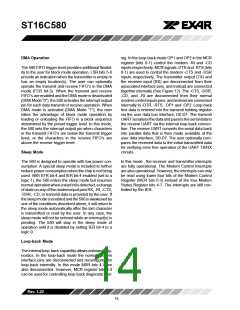
With the Auto RTS function enabled, an interrupt is
generated when the receive FIFO reaches the pro-
grammed trigger level. The -RTS pin will not be forced
to a logic 1 (RTS Off), until the receive FIFO reaches
the next trigger level. However, the -RTS pin will
return to a logic 0 after the data buffer (FIFO) is
unloaded to the next trigger level below the pro-
grammed trigger level. However, under the above
described conditions the 580 will continue to accept
data until the receive FIFO is full.
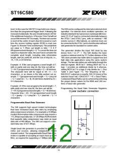
Selected
Trigger
INT
Pin
-RTS
Logic “1”
-RTS
Logic “0”
Level
Activation
(characters) (characters)
(characters)
1
4
8
1
4
8
4
8
14
14
0
1
4
8
14
14
Rev.1.20
10

 EXAR [ EXAR CORPORATION ]