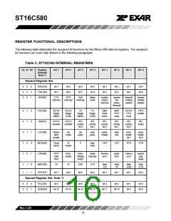
ST16C580
DMA Operation
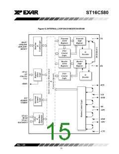
ing. In the loop-back mode OP1 and OP2 in the MCR
register (bits 0-1) control the modem -RI and -CD
inputs respectively. MCR signals -DTR and -RTS (bits
0-1) are used to control the modem -CTS and -DSR
inputs respectively. The transmitter output (TX) and
the receiver input (RX) are disconnected from their
associated interface pins, and instead are connected
together internally (See Figure 12). The -CTS, -DSR,
-CD, and -RI are disconnected from their normal
modemcontrolinputspins, andinsteadareconnected
internally to -DTR, -RTS, -OP1 and -OP2. Loop-back
test data is entered into the transmit holding register
via the user data bus interface, D0-D7. The transmit
UART serializes the data and passes the serial data to
the receive UART via the internal loop-back connec-
tion. The receive UART converts the serial data back
into parallel data that is then made available at the
user data interface, D0-D7. The user optionally com-
pares the received data to the initial transmitted data
for verifying error free operation of the UART TX/RX
circuits.
The 580 FIFO trigger level provides additional flexibil-
ity to the user for block mode operation. LSR bits 5-6
provide an indication when the transmitter is empty or
has an empty location(s). The user can optionally
operate the transmit and receive FIFO’s in the DMA
mode (FCR bit-3). When the transmit and receive
FIFO’s are enabled and the DMA mode is deactivated
(DMA Mode “0”), the 580 activates the interrupt output
pin for each data transmit or receive operation. When
DMA mode is activated (DMA Mode “1”), the user
takes the advantage of block mode operation by
loading or unloading the FIFO in a block sequence
determined by the preset trigger level. In this mode,
the 580 sets the interrupt output pin when characters
in the transmit FIFO’s are below the transmit trigger
level, or the characters in the receive FIFO’s are
above the receive trigger level.
Sleep Mode
The 580 is designed to operate with low power con-
sumption. A special sleep mode is included to further
reduce power consumption when the chip is not being
used. With EFR bit-4 and IER bit-4 enabled (set to a
logic 1), the 580 enters the sleep mode but resumes
normaloperationwhenastartbitisdetected,achange
of state on any of the modem input pins RX, -RI, -CTS,
-DSR, -CD, or transmit data is provided by the user. If
thesleepmodeisenabledandthe580isawakenedby
one of the conditions described above, it will return to
the sleep mode automatically after the last character
is transmitted or read by the user. In any case, the
sleep mode will not be entered while an interrupt(s) is
pending. The 580 will stay in the sleep mode of
operation until it is disabled by setting IER bit-4 to a
logic 0.
In this mode , the receiver and transmitter interrupts
are fully operational. The Modem Control Interrupts
are also operational. However, the interrupts can only
be read using lower four bits of the Modem Control
Register (MCR bits 0-3) instead of the four Modem
Status Register bits 4-7. The interrupts are still con-
trolled by the IER.
Loop-back Mode
The internal loop-back capability allows onboard diag-
nostics. In the loop-back mode the normal modem
interface pins are disconnected and reconfigured for
loop-back internally. In this mode MSR bits 4-7 are
also disconnected. However, MCR register bits 0-3
can be used for controlling loop-back diagnostic test-
Rev.1.20
14

 EXAR [ EXAR CORPORATION ]