Operation
I/O support
In this example, note the following:
83 indicates RX Packet: 16-bit Address I/O frame (0x83).
00 00 indicates 16-bit source address.
00 indicates RSSI (does not apply).
00 indicates options.
01 indicates the number of samples.
03 3E mask to indicate which lines are sampled (A0, D8, D5, D4, D3, D2, and D1).
01 2A digital sample that indicates that D8 is high, D5 is high, D4 is low, D3 is high, D2 is low,
and D1 is high.
02 10 indicates that A0 has input voltage nearly half of capacity, where 03 FF would indicate
the full voltage of 1.2 V = 1200 mV.
For a remote IS command sent to the device listed above with the same configuration, the output is:
7E 00 16 97 01 00 13 A2 00 40 E3 C0 15 00 00 49 53 00 01 03 3E 01 2A 02 10 9F
In this example, note the following:
97 indicates Remote AT Command Response frame (0x97).
01 is the frame ID.
00 13 A2 00 40 E3 C0 15 is the 64-bit source address.
00 00 indicates 16-bit source address.
49 53 (IS) indicates command response to the IS command.
00 indicates the status is OK.
01 indicates the number of samples.
03 3E mask to indicate which lines are sampled (A0, D8, D5, D4, D3, D2, and D1).
01 2A digital sample that indicates that D8 is high, D5 is high, D4 is low, D3 is high, D2 is low,
and D1 is high.
02 10 indicates that A0 has input voltage about half of capacity, where 03 FF would indicate
full voltage of 1.2 V = 1200 mV.
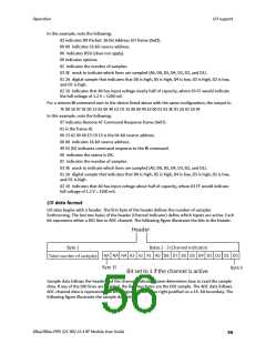
I/O data format
I/O data begins with a header. The first byte of the header defines the number of samples
forthcoming. The last two bytes of the header (Channel Indicator) define which inputs are active. Each
bit represents either a DIO line or ADC channel. The following figure illustrates the bits in the header.
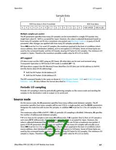
Sample data follows the header and the channel indicator frame determines how to read the sample
data. If any of the DIO lines are enabled, the first two bytes are the DIO sample. The ADC data follows.
ADC channel data is represented as an unsigned 10-bit value right-justified on a 16- bit boundary. The
following figure illustrates the sample data bits.
XBee/XBee-PRO S2C 802.15.4 RF Module User Guide
56

 ETC [ ETC ]