Operation
I/O support
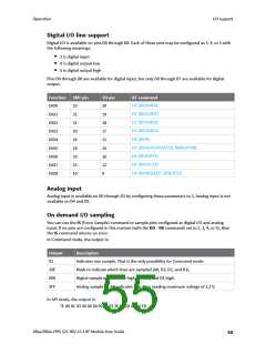
Digital I/O line support
Digital I/O is available on pins D0 through D8. Each of these pins may be configured as 3, 4, or 5 with
the following meanings:
n
3 is digital input
n
4 is digital output low
n
5 is digital output high
Pins D0 through D8 are available for digital input, but only D0 through D7 are available for digital
output.
Function
DIO0
DIO1
DIO2
DIO3
DIO4
DIO5
DIO6
DIO7
DIO8
SMT pin
33
TH pin
20
AT command
D0 (DIO0/AD0)
D1 (DIO1/AD1)
32
19
D2 (DIO2/AD2)
31
18
D3 (DIO3/AD3)
30
17
D4 (DIO4)
24
11
D5 (DIO5/ASSOCIATED_INDICATOR)
D6 (DIO6/RTS)
28
15
29
16
D7 (DIO7/CTS)
25
12
D8 (DIO8/SLEEP_REQUEST)
10
9
Analog input
Analog input is available on D0 through D3 by configuring these parameters to 2. Analog input is not
available on D4 and D5.
On demand I/O sampling
You can use the IS (Force Sample) command to sample pins configured as digital I/O and analog
input. If no pins are configured in this manner (with the DO - D8 commands set to 2, 3, 4, or 5), then
the IS command returns an error.
In Command mode, the output is:
Output
01
Description
Indicates one sample. That is the only possibility for Command mode.
Mask to indicate which lines are sampled (A0, D3, D2, and D1).
Digital sample indicates D3 high, D2 low, and D1 high.
Analog sample for A0 indicates that A0 is reading maximum voltage of 1.2 V.
20E
00A
3FF
In API mode, the output is:
7E 00 0C 83 00 00 00 00 01 03 3E 01 2A 02 10 FD
XBee/XBee-PRO S2C 802.15.4 RF Module User Guide
55

 ETC [ ETC ]