Operation
SPI operation
Asynchronous Parameters
Asynchronous communication over a UART is configured with a start bit, data bits, parity, stop bits,
and baud rate. Out of these, only parity and baud rate are configurable on the device for 802.15.4. This
means that the connecting micro-controller must match the the start bits (1), the data bits (8), and the
stop bits (1) of the device for proper communication.
Parity
Use the NB command to configure parity; see NB (Parity).
SPI operation
This section specifies how SPI is implemented on the device, what the SPI signals are, and how full
duplex operations work.
SPI signals
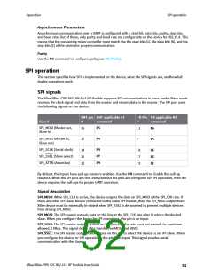
The XBee/XBee-PRO S2C 802.15.4 RF Module supports SPI communications in slave mode. Slave mode
receives the clock signal and data from the master and returns data to the master. The SPI port uses
the following signals on the device:
SMT pin SMT applicable AT
TH Pin TH applicable AT
Signal
#
command
#
command
SPI_MOSI (Master out,
Slave in)
P6
16
11
D4
SPI_MISO (Master in,
Slave out)
P5
17
4
P2
SPI_SCLK (Serial clock)
SPI_SSEL (Slave select)
SPI_ATTN (Attention)
P8
P7
P9
14
15
12
18
17
19
D2
D3
D1
By default, the inputs have pull-up resistors enabled. Use the PR command to disable the pull-up
resistors. When the SPI pins are not connected but the pins are configured for SPI operation, then the
device requires the pull-ups for proper UART operation.
Signal description
SPI_MISO: When SPI_CLK is active, the device outputs the data on SPI_MISO at the SPI_CLK rate. If
there are other SPI slave devices connected to the same SPI master, then the SPI_MISO output from
XBee device must be externally tri-stated when SPI_SSEL is de-asserted to prevent multiple devices
from driving SPI_MISO.
SPI_MOSI: The SPI master outputs data on this line at the SPI_CLK rate after it selects the desired
slave. When you configure the device for SPI operations, this pin is an input.
SPI_SCLK: The SPI master outputs a clock on this pin, and the rate must not exceed the maximum
allowed, 5 Mb/s. This signal clocks data transfers on MOSI and MISO.
SPI_SSEL: The SPI master outputs a low signal on this pin to select the device as an SPI slave. When
you configure the device for SPI operations, this pin is an input. This signal enables serial
communication with the slave.
XBee/XBee-PRO S2C 802.15.4 RF Module User Guide
52

 ETC [ ETC ]