Page 30
Epson Research and Development
Vancouver Design Center
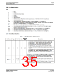
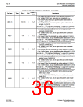
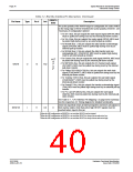
Table 5-1: Host Bus Interface Pin Descriptions (Continued)
RESET#
State
Pin Name
Type
Pin #
Cell
Description
• For Philips PR31500/31700 Bus, these pins are connected to VDD
.
• For Toshiba TX3912 Bus, these pins are connected to VDD
.
• For PowerPC Bus, these pins input the system address bits 15
through 18 (A[15:18]).
AB[16:13]
I
115-118
C
Hi-Z
Hi-Z
Hi-Z
Hi-Z
• For all other busses, these pins input the system address bits 16
through 13 (A[16:13]).
See Table 5-7:, “CPU Interface Pin Mapping,” on page 40 for summary.
See the respective AC Timing diagram for detailed functionality.
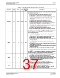
• For Philips PR31500/31700 Bus, this pin inputs the IO write
command (/CARDIOWR).
• For Toshiba TX3912 Bus, this pin inputs the IO write command
(CARDIOWR*).
AB17
I
I
I
114
113
112
C
C
C
• For PowerPC Bus, this pin inputs the system address bit 14 (A14).
• For all other busses, this pin inputs the system address bit 17 (A17).
See Table 5-7:, “CPU Interface Pin Mapping,” on page 40 for summary.
See the respective AC Timing diagram for detailed functionality.
• For Philips PR31500/31700 Bus, this pin inputs the IO read
command (/CARDIORD).
• For Toshiba TX3912 Bus, this pin inputs the IO read command
(CARDIORD*).
AB18
• For PowerPC Bus, this pin inputs the system address bit 13 (A13).
• For all other busses, this pin inputs the system address bit 18 (A18).
See Table 5-7:, “CPU Interface Pin Mapping,” on page 40 for summary.
See the respective AC Timing diagram for detailed functionality.
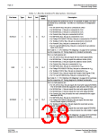
• For Philips PR31500/31700 Bus, this pin inputs the card control
register access (/CARDREG).
• For Toshiba TX3912 Bus, this pin inputs the card control register
access (CARDREG*).
AB19
• For PowerPC Bus, this pin inputs the system address bit 12 (A12).
• For all other busses, this pin inputs the system address bit 19 (A19).
See Table 5-7:, “CPU Interface Pin Mapping,” on page 40 for summary.
See the respective AC Timing diagram for detailed functionality.
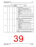
• For the MIPS/ISA Bus, this pin inputs system address bit 20. Note
that for the ISA Bus, the unlatched LA20 must first be latched
before input to AB20.
• For Philips PR31500/31700 Bus, this pin inputs the address latch
enable (ALE).
• For Toshiba TX3912 Bus, this pin inputs the address latch enable
(ALE).
AB20
I
111
C
Hi-Z
• For PowerPC Bus, this pin inputs the system address bit 11 (A11).
• For all other busses, this pin inputs the system address bit 20 (A20).
See Table 5-7:, “CPU Interface Pin Mapping,” on page 40 for summary.
See the respective AC Timing diagram for detailed functionality.
S1D13506
X25B-A-001-10
Hardware Functional Specification
Issue Date: 01/02/06

 EPSON [ EPSON COMPANY ]