Epson Research and Development
Page 41
Vancouver Design Center
8.2 Registers
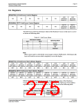
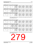
REG[070h] LCD Ink/Cursor Control Register
LCD
LCD
n/a
n/a
n/a
n/a
n/a
n/a
n/a
n/a
Ink/Cursor
Mode Bit 1
Ink/Cursor
Mode Bit 0
REG[080h] CRT/TV Ink/Cursor Control Register
n/a n/a n/a n/a
CRT/TV
Ink/Cursor
Mode Bit 1
CRT/TV
Ink/Cursor
Mode Bit 0
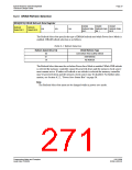
The Ink/Cursor mode bits determine which of the Hardware Cursor or Ink Layer is active
as shown in following table.
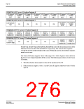
Table 8-1: Ink/Cursor Mode
Ink/Cursor Control
Operating Mode
bit 1
bit 0
0
0
1
1
0
1
0
1
Inactive
Cursor
Ink
Reserved
Note
When cursor mode is selected the cursor image is always 64x64 pixels. Selecting an ink
layer will result in an area which completely covers the display.
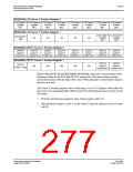
REG[071h] LCD Ink/Cursor Start Address Register
LCD
LCD
LCD
LCD
LCD
LCD
LCD
LCD
Ink/Cursor
Ink/Cursor
Ink/Cursor
Ink/Cursor
Ink/Cursor
Ink/Cursor
Ink/Cursor
Ink/Cursor
Start Address Start Address Start Address Start Address Start Address Start Address Start Address Start Address
Bit 7
Bit 6
Bit 5
Bit 4
Bit 3
Bit 2
Bit 1
Bit 0
REG[081h] CRT/TV Ink/Cursor Start Address Register
CRT/TV
CRT/TV
CRT/TV
CRT/TV
CRT/TV
CRT/TV
CRT/TV
CRT/TV
Ink/Cursor
Ink/Cursor
Ink/Cursor
Ink/Cursor
Ink/Cursor
Ink/Cursor
Ink/Cursor
Ink/Cursor
Start Address Start Address Start Address Start Address Start Address Start Address Start Address Start Address
Bit 7 Bit 6 Bit 5 Bit 4 Bit 3 Bit 2 Bit 1 Bit 0
REG[071h] and REG[081h] determine the display buffer location of the Hardware
Cursor/Ink Layer for the LCD and CRT/TV respectively. The Ink/Cursor Start Address
register does not contain an actual address, but a value based on the following table.
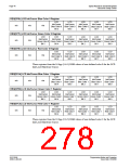
Table 8-2: Cursor/Ink Start Address Encoding
Ink/Cursor Start Address Bits [7:0]
Start Address (Bytes)
0
Display Buffer Size - 1024
Display Buffer Size - (n ×
1 - FFh
8192)
Programming Notes and Examples
Issue Date: 01/02/06
S1D13506
X25B-G-003-03

 EPSON [ EPSON COMPANY ]