Epson Research and Development
Page 43
Vancouver Design Center
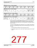
REG[074h] LCD Cursor Y Position Register 0
LCD Cursor Y LCD Cursor Y LCD Cursor Y LCD Cursor Y LCD Cursor Y LCD Cursor Y LCD Cursor Y LCD Cursor Y
Position
Bit 7
Position
Bit 6
Position
Bit 5
Position
Bit 4
Position
Bit 3
Position
Bit 2
Position
Bit 1
Position
Bit 0
REG[075h] LCD Cursor Y Position Register 1
LCD Cursor Y LCD Cursor Y
LCD Cursor Y
n/a
n/a
n/a
n/a
n/a
Position
Bit 9
Position
Bit 8
Sign
REG[084h] CRT/TV Cursor Y Position Register 0
CRT/TV
Cursor Y
CRT/TV
Cursor Y
CRT/TV
Cursor Y
CRT/TV
Cursor Y
CRT/TV
Cursor Y
CRT/TV
Cursor Y
CRT/TV
Cursor Y
CRT/TV
Cursor Y
Position Bit 7 Position Bit 6 Position Bit 5 Position Bit 4 Position Bit 3 Position Bit 2 Position Bit 1 Position Bit 0
REG[085h] CRT/TV Cursor Y Position Register 1
CRT/TV
Cursor Y
Position Bit 9 Position Bit 8
CRT/TV
Cursor Y
CRT/TV
Cursor Y Sign
n/a
n/a
n/a
n/a
n/a
REG[074h], REG[075h] and REG[084h], REG[085h] control the vertical position of the
Hardware Cursor for the LCD and CRT/TV respectively. The value in these registers
specify the location of the top edge of the cursor. When ink mode is selected these registers
must be set to zero.
The Cursor Y Position supports values of the range -63 to 1023. Negative values allow for
the Cursor to be clipped (partially off the screen). The following procedure sets the Cursor
X Position.
1. Write the absolute (non-negative) value of the position in bits 9-0.
2. If the position is negative, write a 1 in the Cursor Y Sign bit; otherwise write a 0 to the
sign bit.
Programming Notes and Examples
Issue Date: 01/02/06
S1D13506
X25B-G-003-03

 EPSON [ EPSON COMPANY ]