epc3xx
Application Information
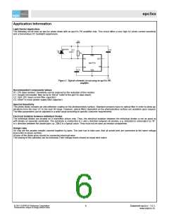
Light Barrier Application
The following circuit uses an epc3xx photo diode with an epc13x PD amplifier chip. This circuit offers a very high AC photo current sensitivity
and a tremendous DC backlight suppression.
5V
epc3xx
C1
C3
R1
VDD
PD
CN
OUT
VN
epc13x
C2
VSS
Figure 1: Typical schematic circuit using an epc13x PD
amplifier
Recommended Components Values
R1: 27k (bias resistor). Sensitivity can be reduced by the reduction of this resistor.
C1: Usually not needed. May be up to 100 pF (refer to the epc13x data sheet).
C2: 33nF (DC input current filter capacitor)
C3: 100nF or more (power supply filter capacitor)
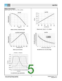
Spectral Sensitivity
This photo diode contains an anti-reflection coating on the photosensitive surface. Standard versions have no optical filter in order to allow ap-
plications from the near UV to the near IR range. However, optical filters deposited on the photosensitive surface are available upon request.
The filter parameters can be adjusted in a wide range according to specific customer requirements.
Electrical Isolation between individual Diodes
The individual diodes are located on a monolithic silicon chip. Thus, the electrical isolation between the individual diodes is not as good as
with diodes on separate substrates. The substrate is conductive in x and y direction between all anodes, e.g. indicated in schematics by “R”.
In x direction between the anode pairs ca. 20kΩ is a typical value. They must not be used as resistor components.
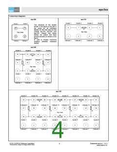
Design rules
On chip are the anodes metallic connect together by pairs. The user has to take care, that all anode pins are connected to the same voltage
level (refer to above section).
All pins of the diode array should be connected electrical-wise.
The biasing of the cathodes can be individual.Their voltage levels should be equal best match.
© 2011 ESPROS Photonics Corporation
Characteristics subject to change without notice
6
Datasheet epc3xx - V2.3
www.espros.ch

 EPC [ ESPROS PHOTONICS CORP ]