EN29SL800
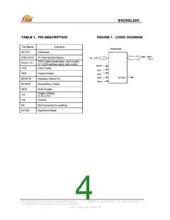
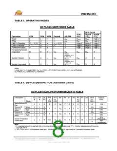
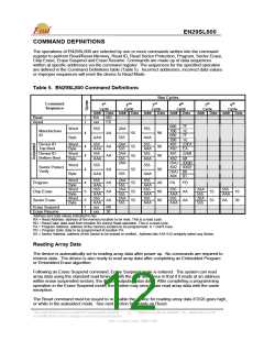
TABLE 3. OPERATING MODES
8M FLASH USER MODE TABLE
DQ8-DQ15
DQ0-
DQ7
Byte#
= VIH
DOUT
DIN
Byte#
= VIL
High-Z
High-Z
Operation
CE#
OE#
WE# Reset#
A0-A18
Read
Write
L
L
L
H
L
X
H
X
H
H
AIN
AIN
X
X
X
DOUT
DIN
H
X
H
X
CMOS Standby
Output Disable
Hardware Reset
Temporary Sector
Unprotect
Vcc ± 0.2V
L
X
Vcc± 0.2V
H
L
High-Z
High-Z
High-Z
High-Z High-Z
High-Z High-Z
High-Z High-Z
X
L
L
X
H
H
X
L
L
VID
VID
VID
AIN
Sector
Address, A6 =
L, A1 = H,
A0 = L
DIN
DIN
DIN
DIN
X
X
X
X
Sector Protect
Sector
Address, A6 =
L, A1 = H,
A0 = L
Sector Unprotect
X
Notes:
L=logic low= VIL, H=Logic High= VIH, VID =10.0 ± 1.0V, X=Don’t Care (either L or H, but not floating!),
DIN=Data In, DOUT=Data Out, AIN=Address In
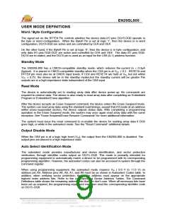
TABLE 4. DEVICE IDENTIFICTION (Autoselect Codes)
8M FLASH MANUFACTURER/DEVICE ID TABLE
Description
CE
#
OE
#
W
E#
A18 A11 A92 A8 A7 A6 A5 A1 A0
DQ8
to
DQ7 to
DQ0
to
to
to
Mode
A12 A10
A2
DQ15
Manufacturer ID:
Eon
L
L
H
X
X
X
X
VID
VID
H1
X
X
X
L
L
X
L
L
L
X
1Ch
Device ID
(top boot
block)
Device ID
(bottom boot
block)
Word
Byte
Word
Byte
L
L
L
L
L
L
L
L
H
H
H
H
22h
X
EAh
EAh
6Bh
6Bh
X
H
22h
X
X
X
X
VID
VID
X
X
X
X
L
L
X
X
L
H
L
01h
(Protected)
00h
(Unprotected)
X
X
Sector Protection
Verification
L
L
H
SA
H
Note:
1. If a manufacturing ID is read with A8=L, the chip will output a configuration code 7Fh. A further Manufacturing ID must be
read with A8=H.
2. A9 = VID is for HV A9 Autoselect mode only. A9 must be ≤ Vcc (CMOS logic level) for Command Autoselect Mode.
This Data Sheet may be revised by subsequent versions
or modifications due to changes in technical specifications.
©2004 Eon Silicon Solution, Inc., www.essi.com.tw
8
Rev. D, Issue Date: 2006/11/06

 EON [ EON SILICON SOLUTION INC. ]