EN29SL800
After an erase-suspended program operation is complete, the system can once again read array
data within non-suspended sectors. The system can determine the status of the program operation
using the DQ7 or DQ6 status bits, just as in the standard program operation. See “Write Operation
Status” for more information. The Autoselect command is not supported during Erase Suspend
Mode.
The system must write the Erase Resume command (address bits are don’t-care) to exit the erase
suspend mode and continue the sector erase operation. Further writes of the Resume command are
ignored. Another Erase Suspend command can be written after the device has resumed erasing.
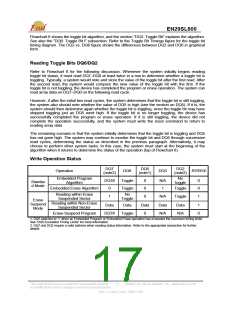
WRITE OPERATION STATUS
DQ7: DATA# Polling
The EN29SL800 provides DATA# polling on DQ7 to indicate the status of the embedded operations.
The DATA# Polling feature is active during the embedded Programming, Sector Erase, Chip Erase,
and Erase Suspend. (See Table 6)
When the embedded Programming is in progress, an attempt to read the device will produce the
complement of the data last written to DQ7. Upon the completion of the embedded Programming,
an attempt to read the device will produce the true data written to DQ7. For the embedded
Programming, DATA# polling is valid after the rising edge of the fourth WE# or CE# pulse in the
four-cycle sequence.
When the embedded Erase is in progress, an attempt to read the device will produce a “0” at the
DQ7 output. Upon the completion of the embedded Erase, the device will produce the “1” at the DQ7
output during the read cycles. For Chip Erase, the DATA# polling is valid after the rising edge of the
sixth WE# or CE# pulse in the six-cycle sequence. DATA# polling is valid after the last rising edge of
the WE# or CE# pulse for chip erase or sector erase.
DATA# Polling must be performed at any address within a sector that is being programmed or
erased and not a protected sector. Otherwise, DATA# polling may give an inaccurate result if the
address used is in a protected sector.
Just prior to the completion of the embedded operations, DQ7 may change asynchronously when
the output enable (OE#) is low. This means that the device is driving status information on DQ7 at
one instant of time and valid data at the next instant of time. Depending on when the system
samples the DQ7 output, it may read the status of valid data. Even if the device has completed the
embedded operations and DQ7 has a valid data, the data output on DQ0-DQ6 may be still invalid.
The valid data on DQ0-DQ7 will be read on the subsequent read attempts.
The flowchart for DATA# Polling (DQ7) is shown on Flowchart 5. The DATA# Polling (DQ7) timing
diagram is shown in Figure 8.
RY/BY#: Ready/Busy
The RY/BY# is a dedicated, open-drain output pin that indicates whether an Embedded Algorithm is
in progress or completed. The RY/BY# status is valid after the rising edge of the final WE# pulse in
the command sequence. Since RY/BY# is an open-drain output, several RY/BY# pins can be tied
together in parallel with a pull-up resistor to Vcc.
In the output-low period, signifying Busy, the device is actively erasing or programming. This
includes programming in the Erase Suspend mode. If the output is high, signifying the Ready, the
device is ready to read array data (including during the Erase Suspend mode), or is in the standby
mode.
This Data Sheet may be revised by subsequent versions
or modifications due to changes in technical specifications.
©2004 Eon Silicon Solution, Inc., www.essi.com.tw
15
Rev. D, Issue Date: 2006/11/06

 EON [ EON SILICON SOLUTION INC. ]