EN25F40
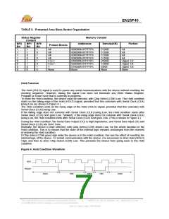
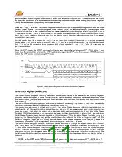
TABLE 3. Protected Area Sizes Sector Organization
Status Register
Content
Memory Content
BP2
Bit
1
1
1
1
0
0
0
BP1
Bit
1
1
0
0
1
1
0
BP0
Bit
1
0
1
0
1
0
1
Addresses
Density(KB)
Portion
Protect Blocks
All
All
All
000000h-0FFFFFh
000000h-0FFFFFh
000000h-0FFFFFh
000000h-0FFFFFh
040000h-07FFFFh
060000h-07FFFFh
070000h-07FFFFh
None
512KB
512KB
512KB
512KB
256KB
128KB
64KB
All
All
All
All
All
4 to 7
6 to 7
7
Upper 1/2
Upper 1/4
Upper 1/8
None
0
0
0
None
None
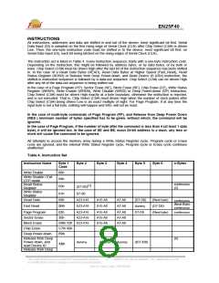
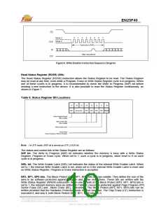
Hold Function
The Hold (HOLD) signal is used to pause any serial communications with the device without resetting the
clocking sequence. However, taking this signal Low does not terminate any Write Status Register,
Program or Erase cycle that is currently in progress.
To enter the Hold condition, the device must be selected, with Chip Select (CS#) Low. The Hold condition
starts on the falling edge of the Hold (HOLD) signal, provided that this coincides with Serial Clock (CLK)
being Low (as shown in Figure 4.).
The Hold condition ends on the rising edge of the Hold (HOLD) signal, provided that this coincides with
Serial Clock (CLK) being Low.
If the falling edge does not coincide with Serial Clock (CLK) being Low, the Hold condition starts after
Serial Clock (CLK) next goes Low. Similarly, if the rising edge does not coincide with Serial Clock (CLK)
being Low, the Hold condition ends after Serial Clock (CLK) next goes Low. (This is shown in Figure 4.).
During the Hold condition, the Serial Data Output (DO) is high impedance, and Serial Data Input (DI) and
Serial Clock (CLK) are Don’t Care.
Normally, the device is kept selected, with Chip Select (CS#) driven Low, for the whole duration of the
Hold condition. This is to ensure that the state of the internal logic remains unchanged from the moment
of entering the Hold condition.
If Chip Select (CS#) goes High while the device is in the Hold condition, this has the effect of resetting the
internal logic of the device. To restart communication with the device, it is necessary to drive Hold (HOLD)
High, and then to drive Chip Select (CS#) Low. This prevents the device from going back to the Hold
condition.
Figure 4. Hold Condition Waveform
This Data Sheet may be revised by subsequent versions
or modifications due to changes in technical specifications.
©2004 Eon Silicon Solution, Inc., www.essi.com.tw
7
Rev. B, Issue Date: 2007/05/09

 EON [ EON SILICON SOLUTION INC. ]